Step 1: Power Off and Remove the Right-Side Cover
Step 2: Remove the Cleaning Liquid Box
Step 3: Remove the Pump Mounting Bracket Assembly
Step 4: Remove and Reconnect the Cleaning Liquid Pump and Moisturizing Liquid Pump
Removing the Leftmost Cleaning Liquid Pump
Removing the Middle Moisture-Keeping Liquid Pump
Step 5: Remove and Discard the Old Waste Ink Pump
Step 6: Install the New Base and Waste Ink Pump
Step 7: Reinstall the Pump Mounting Bracket Assembly
Video link: https://www.youtube.com/watch?v=3_rlTdlFpD0&t=60s
Accessories Introduction
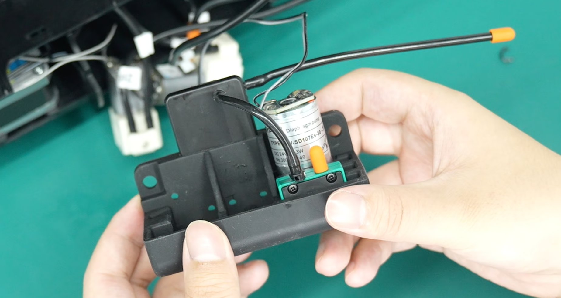
This update adds a filter to the waste ink pump system, requiring the existing base and waste ink pump to be replaced with a new base with the filter pre-installed and a new waste ink pump.
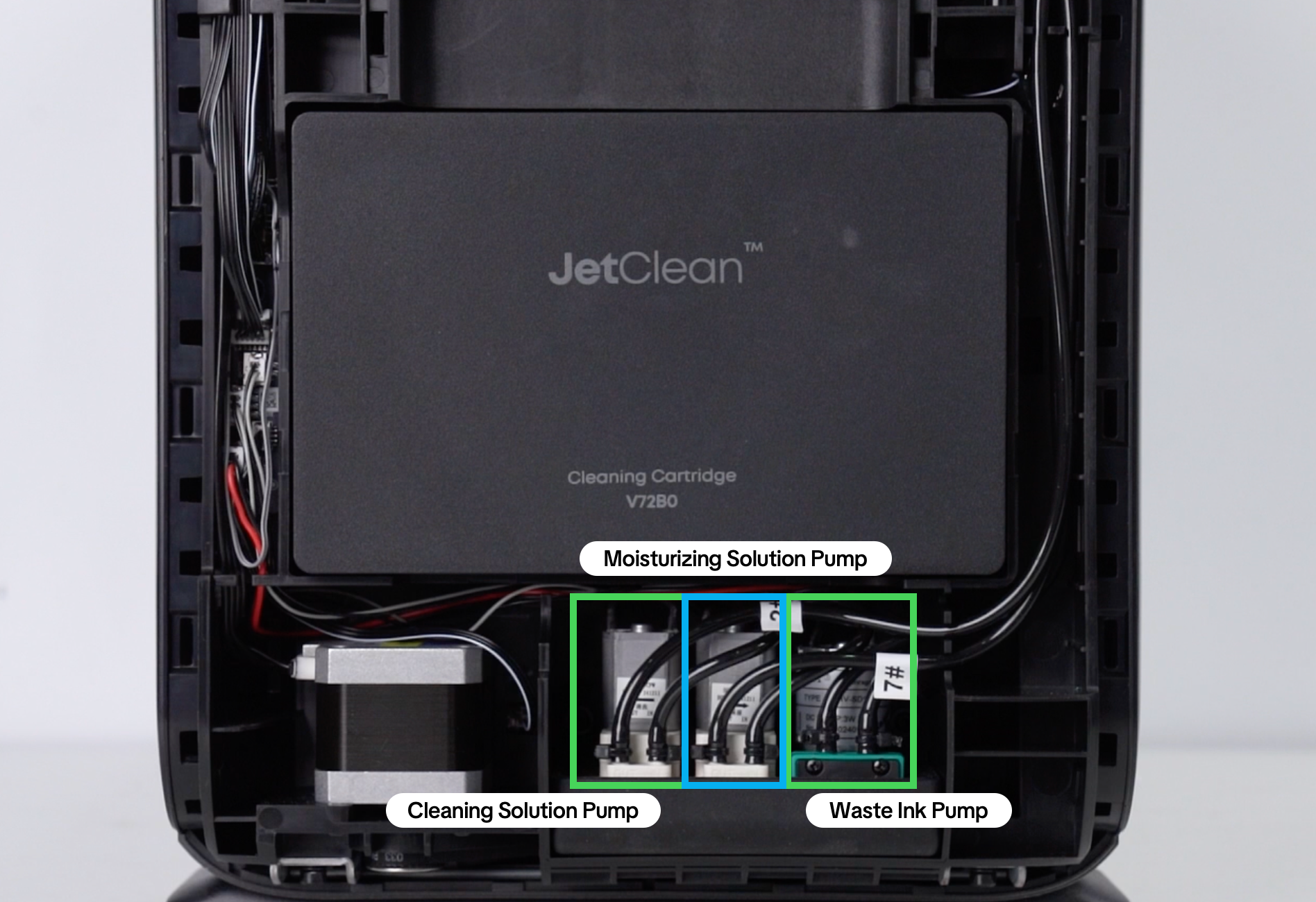
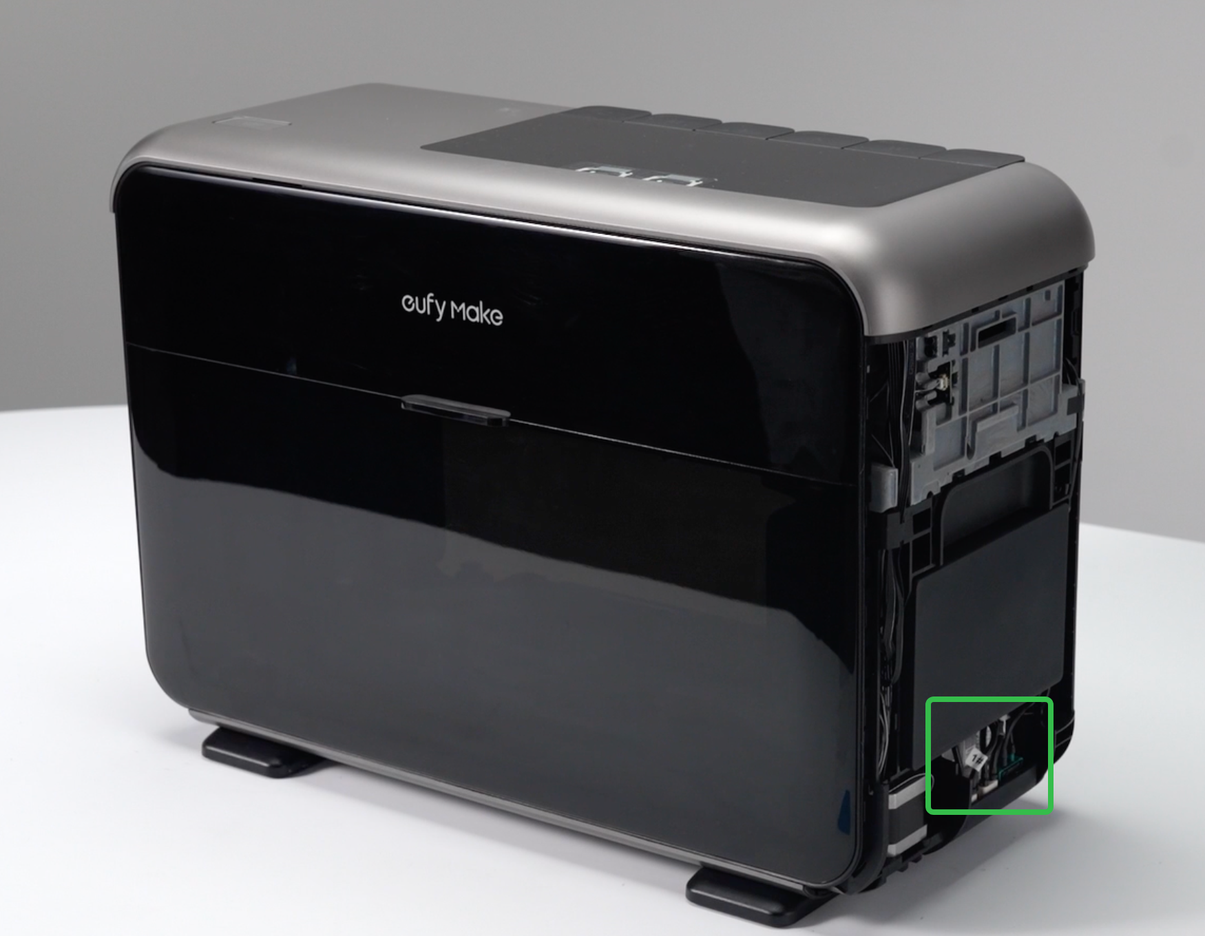
The components are located below the cleaning liquid box on the right side of the machine.
Required Tools
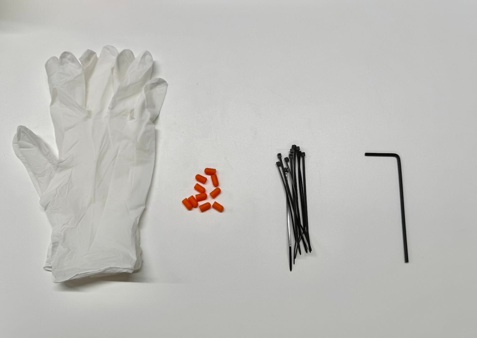
The kit includes a tool kit, a new base, and a new waste ink pump.
The tool kit contains:
-
Disposable nitrile rubber gloves
-
2.0 mm hex (Allen) screwdriver
-
Rubber stoppers
-
Cable ties
Scissors or pliers are not included and must be prepared separately.
Safety Precautions
-
Keep the machine powered off throughout the entire process.
-
Be careful not to connect the ink tubes incorrectly. Before disconnecting any tubes, make sure you remember which port each tube connects to by checking the number labels on the tubes.
-
The cleaning liquid box must be removed first. After removal, plug the three openings with rubber stoppers to prevent liquid from leaking out.
-
Waste ink is corrosive. Wear gloves throughout the procedure.
-
Before cutting the ink tubes, take appropriate protective measures. Keep the tube openings facing upward during the procedure to prevent liquid from contaminating your skin, the equipment, or the work surface.
-
When reinstalling the housing, make sure all wires and ink tubes are properly seated and that none are exposed or pinched.
-
If multiple pumps need to be replaced, replace them one at a time rather than simultaneously to avoid mixing up the ink tubes.
Replacement Steps
Step 1: Power Off and Remove the Right-Side Cover
-
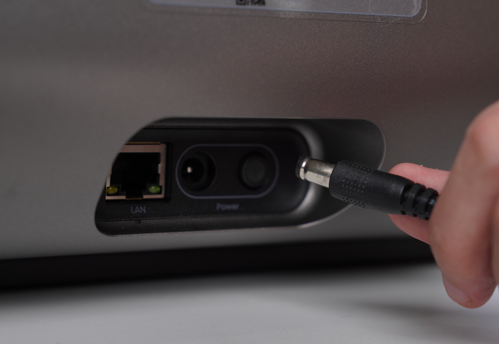
Shut down the machine, unplug the power cord, and make sure the print head is in the moisture-keeping state.
-
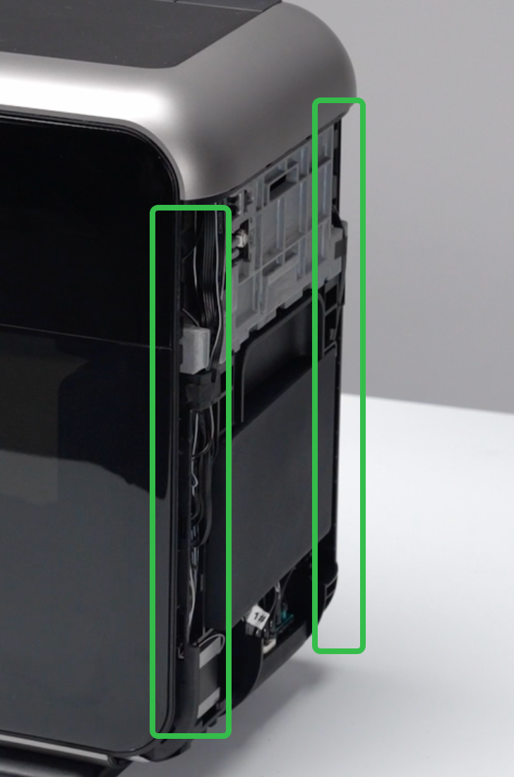
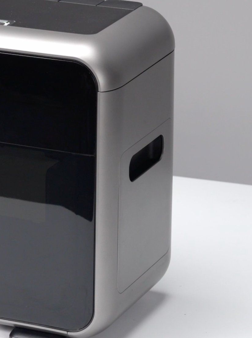
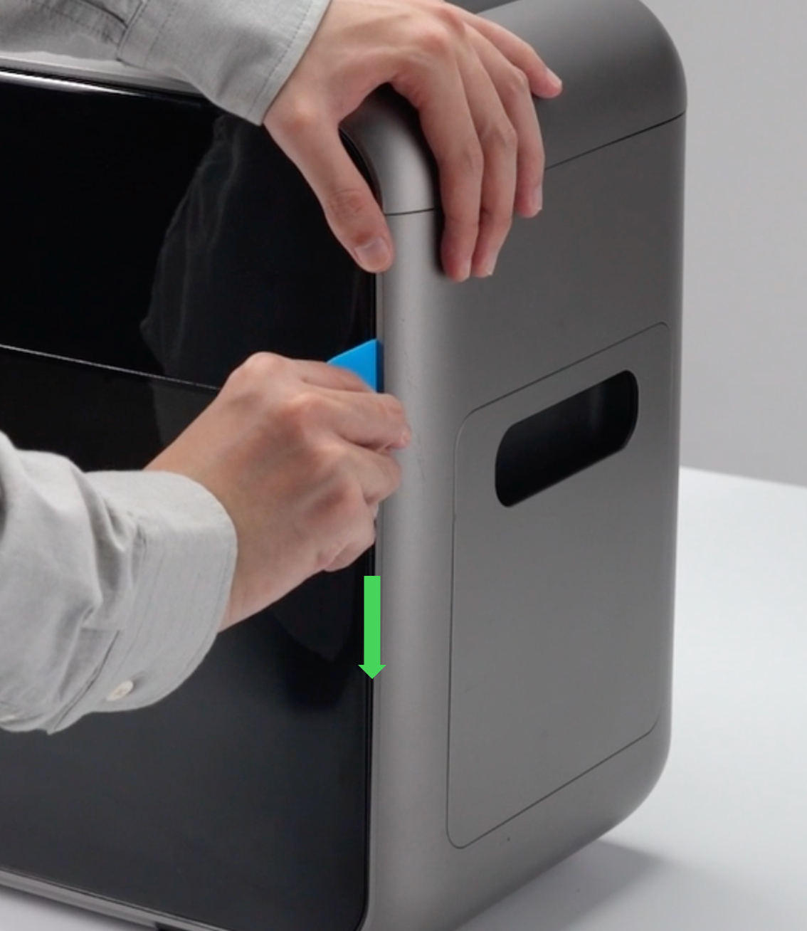
Use a pry tool to open a gap along the left and right edges of the housing, then pull the housing outward from the bottom to remove the right-side cover.

Step 2: Remove the Cleaning Liquid Box
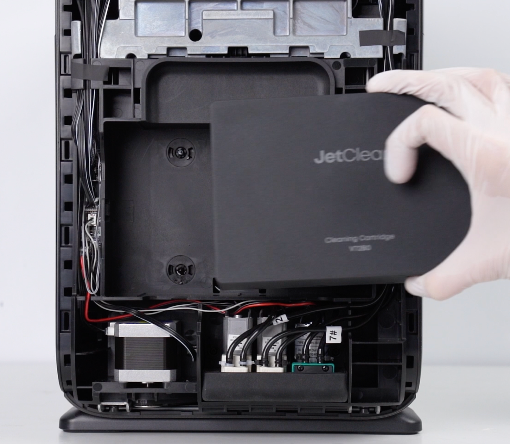
Before performing any pump-related operations, remove the cleaning liquid box. Otherwise, liquid in the box may flow out after the tubes are disconnected.
Step 3: Remove the Pump Mounting Bracket Assembly
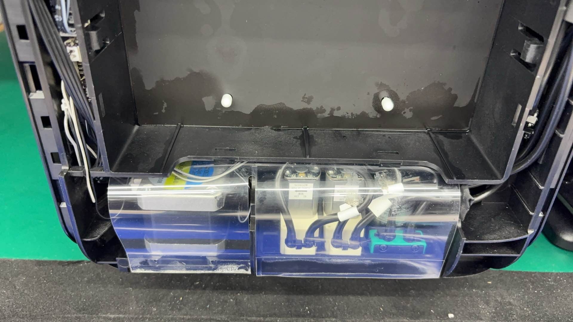
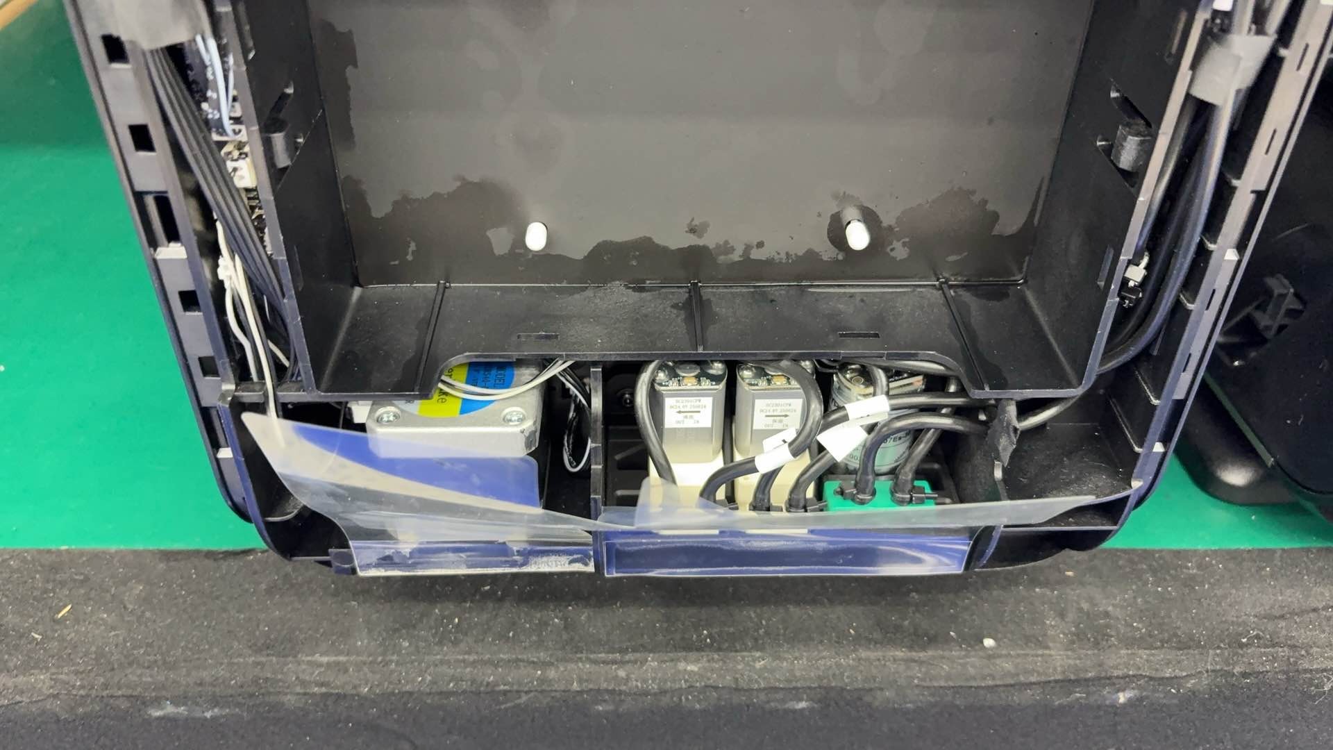
-
Pry open the plastic baffle.
-
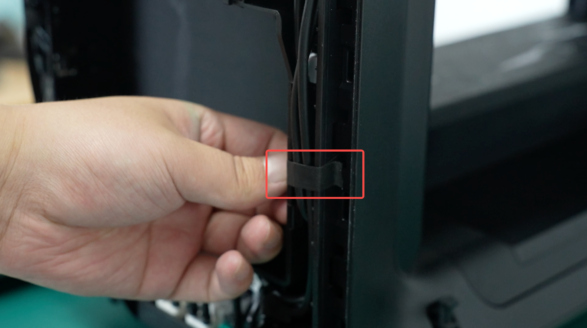
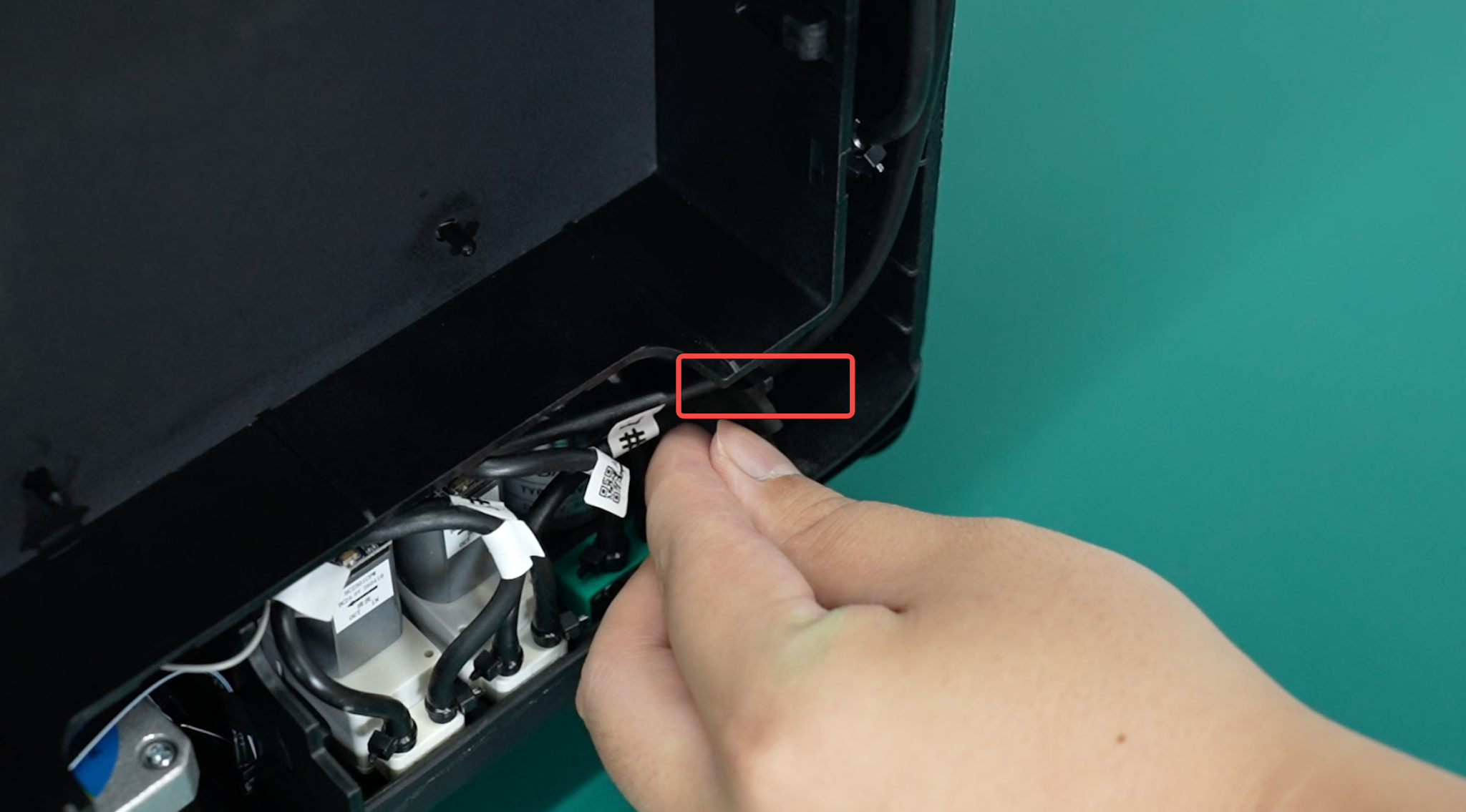
Remove the tape securing the tubes.
-
Remove the two screws and pull the pump mounting bracket assembly out from the bottom.
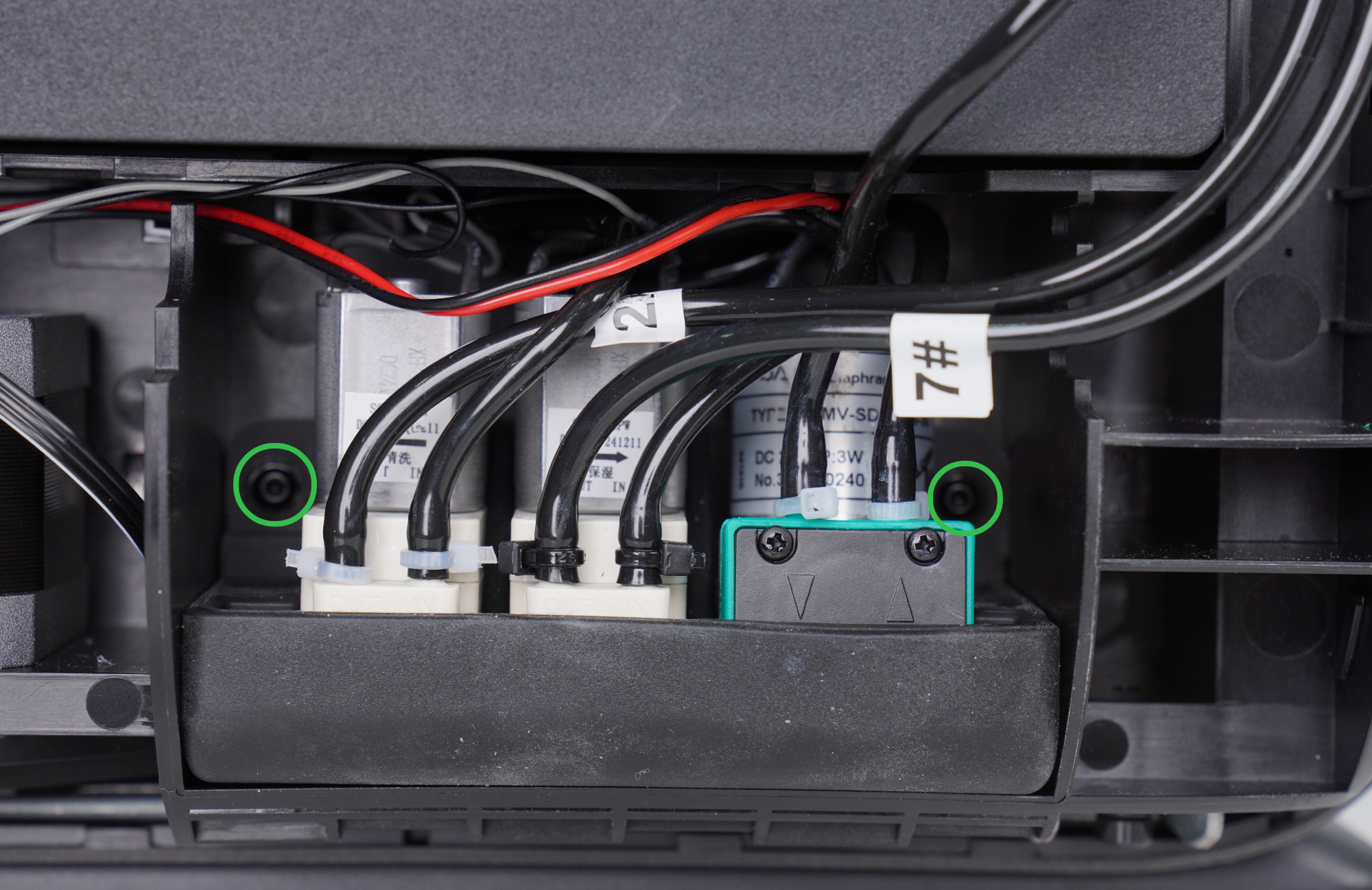
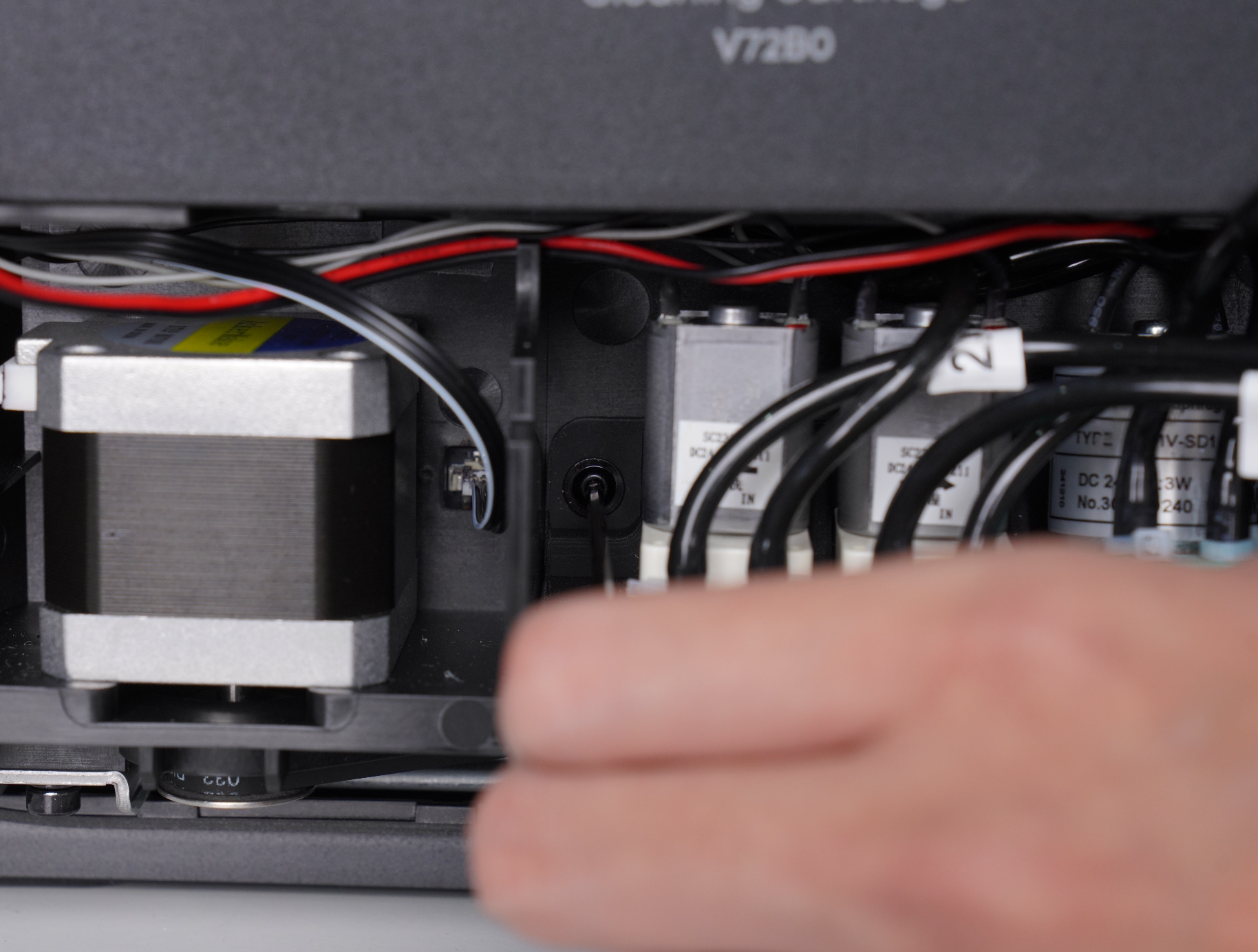
Step 4: Remove and Reconnect the Cleaning Liquid Pump and Moisturizing Liquid Pump
Removing the Leftmost Cleaning Liquid Pump
-
Remove the two mounting screws and take out the pump.
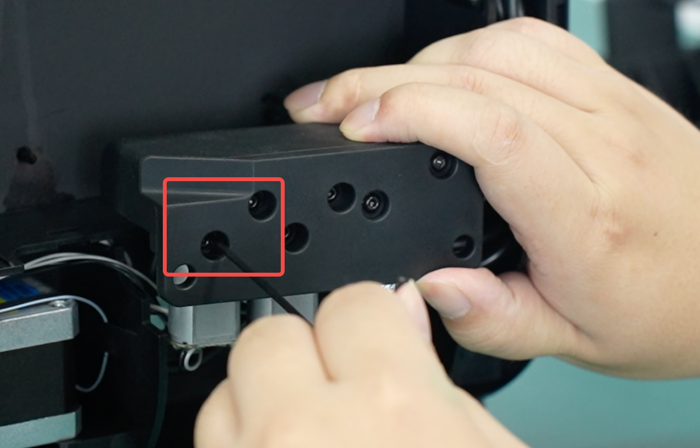
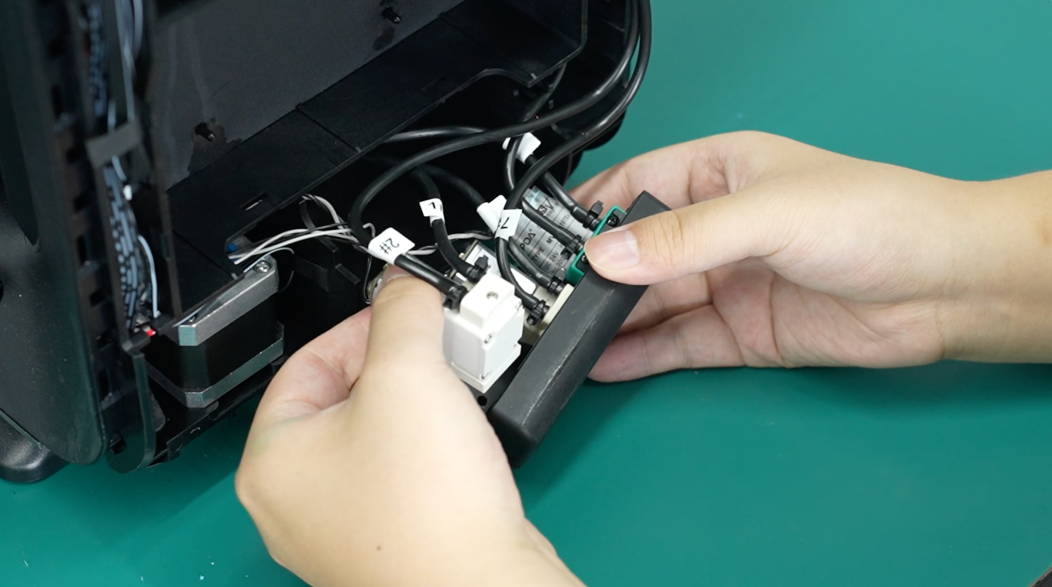
-
Use pliers to cut off the securing cable ties and prepare two rubber stoppers.
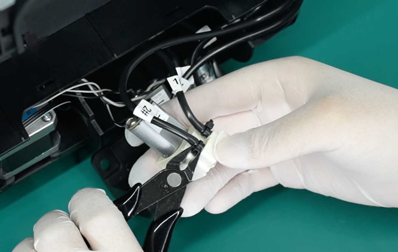
-
Disconnect the tubes and plug the openings with rubber stoppers to prevent liquid from leaking. Make sure you remember which port each tube connects to by checking the number labels.
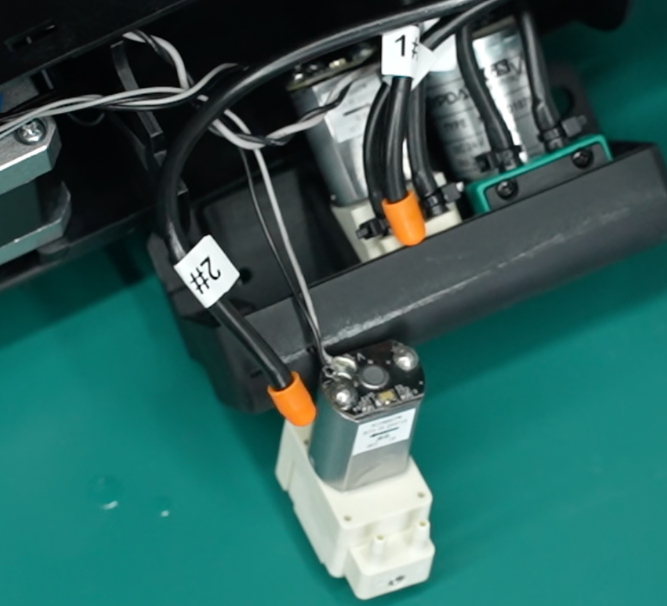
-
Remove the stopper and cut 1–2 cm from the end of each tube. Keep the tube opening facing upward while cutting, then reinstall the stopper when finished.
Note: Keep the tube opening facing upward while cutting to prevent waste liquid from flowing out.
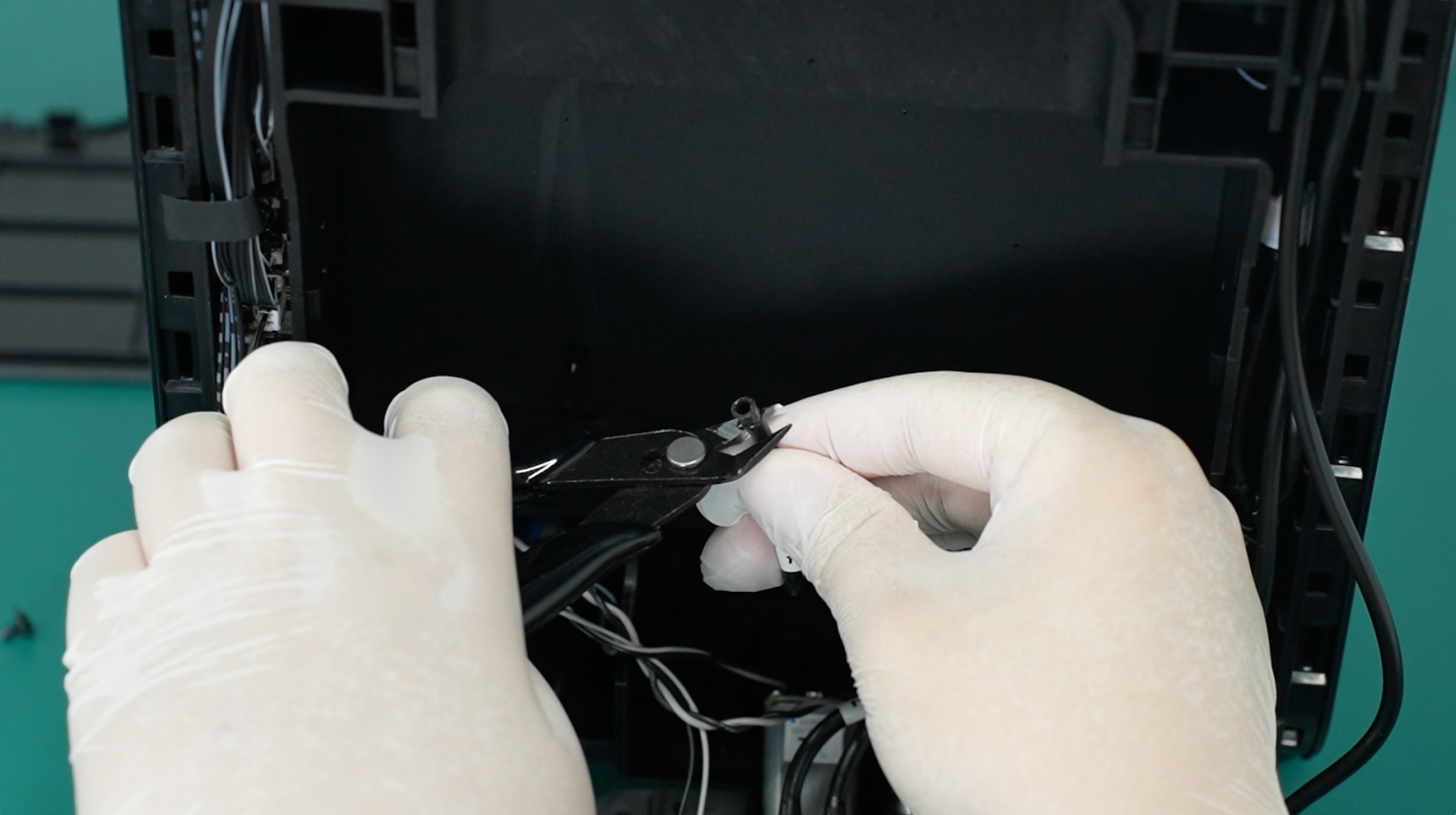
-
Locate the corresponding port for each tube, remove the stopper, and firmly push the tube into place.
Note: The left side is labeled 2#, and the right side is labeled 1#.
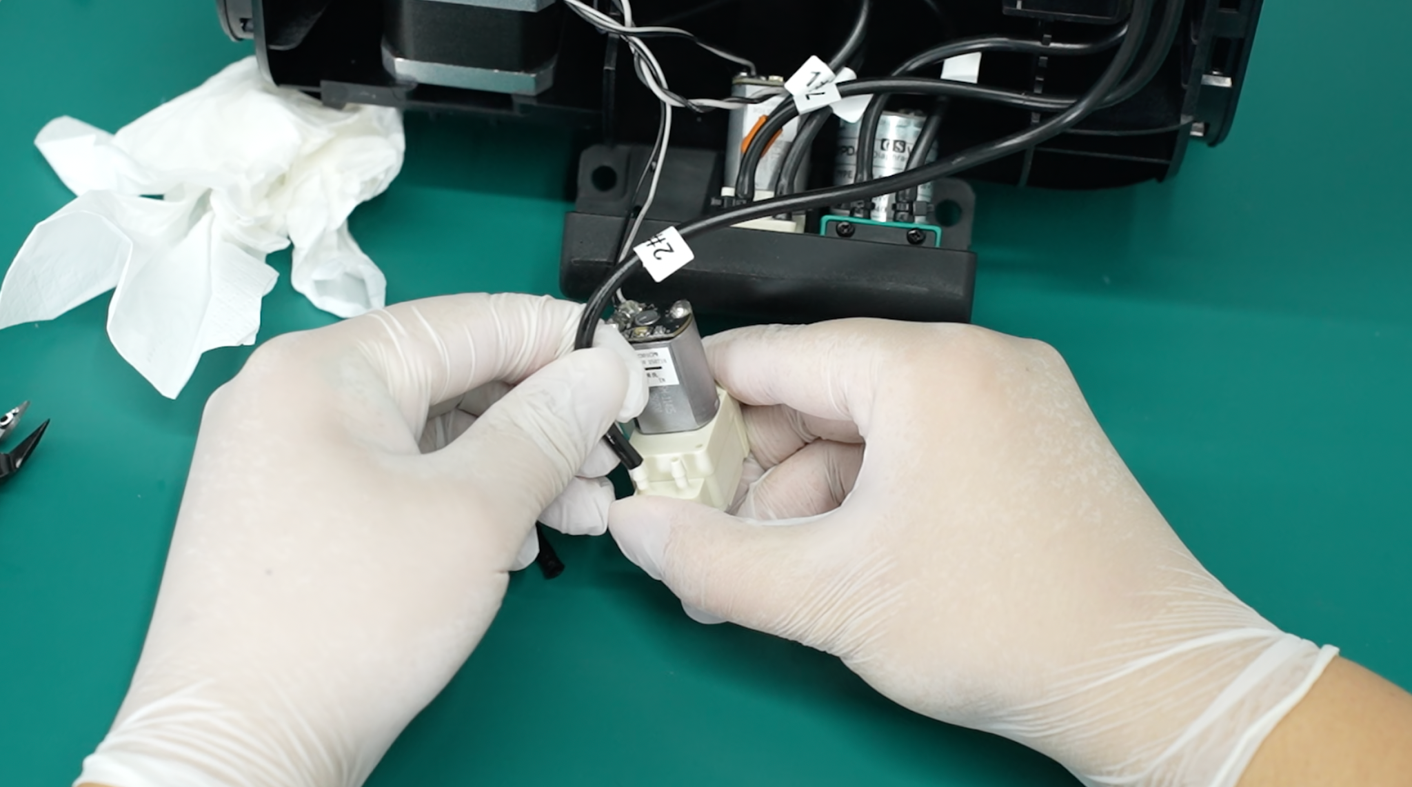
-
Confirm that both tubes on the left pump are firmly connected and that there is no liquid leakage.
Removing the Middle Moisture-Keeping Liquid Pump
-
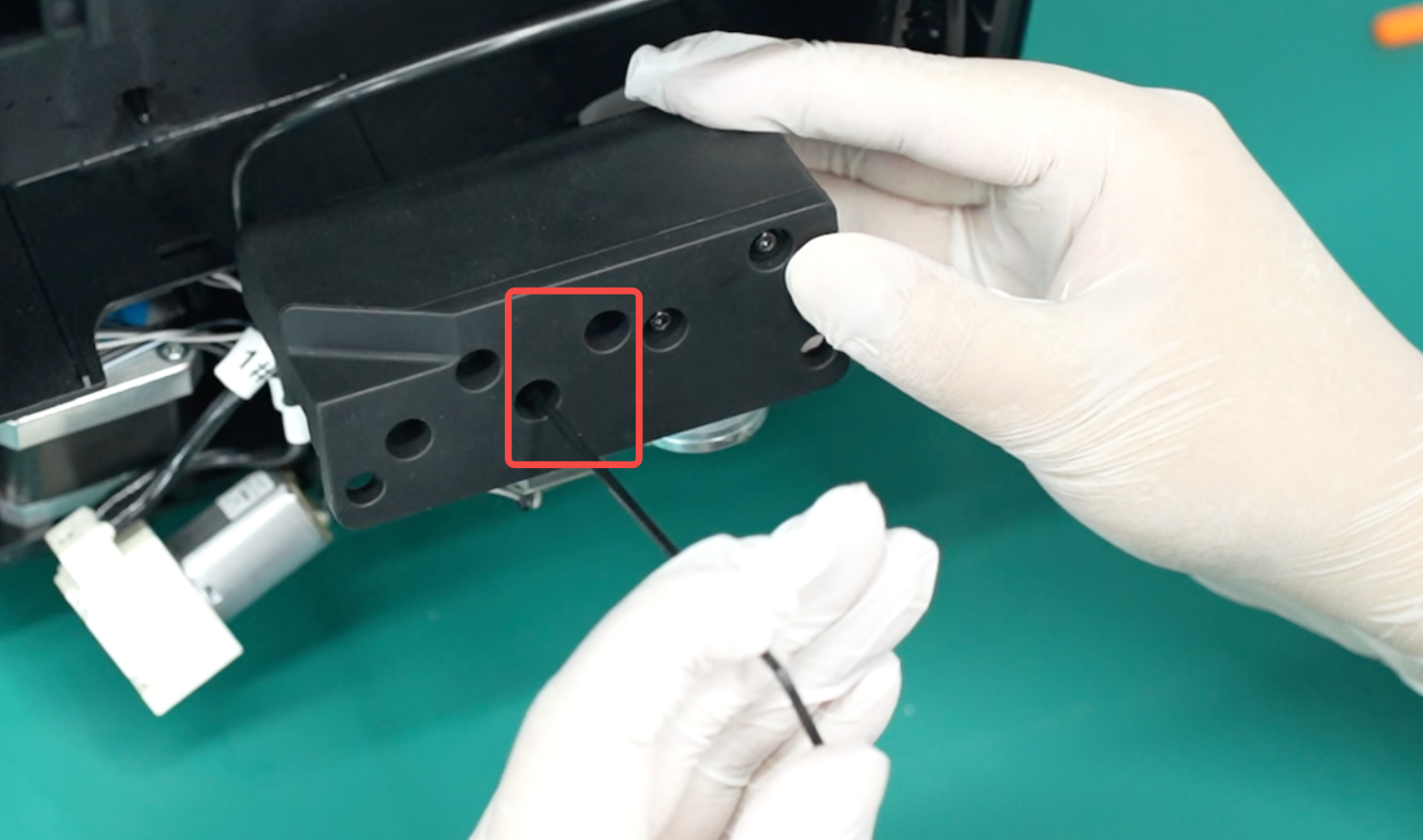
Remove the two mounting screws and take out the pump.
-
Use pliers to cut off the securing cable ties and prepare two rubber stoppers.
-
Disconnect the tubes and plug the openings with rubber stoppers to prevent liquid from leaking. Make sure you remember which port each tube connects to by checking the number labels.
-
Remove the stopper and cut 1–2 cm from the end of each tube. Keep the tube opening facing upward while cutting, then reinstall the stopper when finished.
Note: Keep the tube opening facing upward while cutting to prevent waste liquid from flowing out.
-
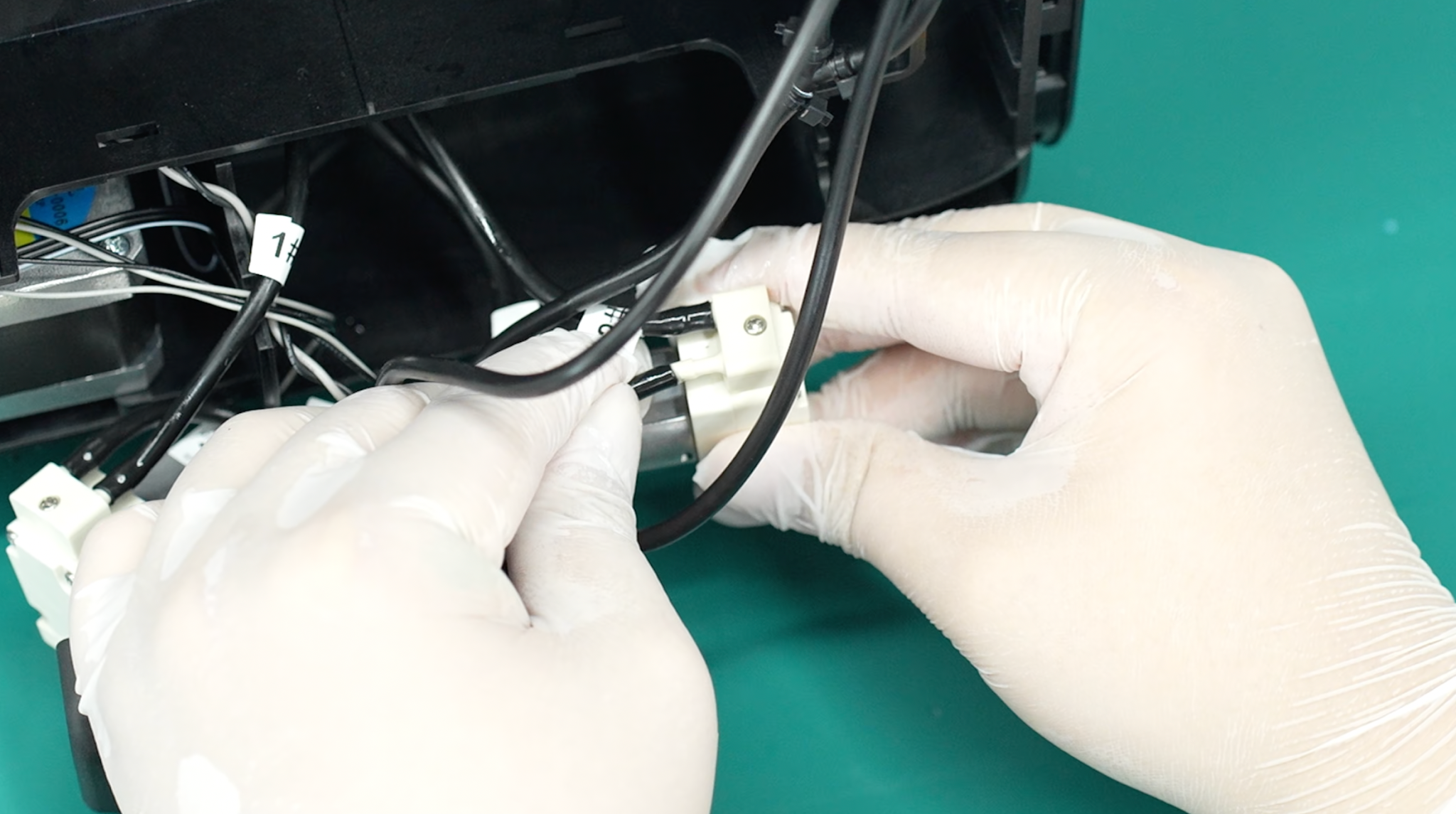
Locate the corresponding port for each tube, remove the stopper, and firmly push the tube into place.
Note: The left side is labeled 7#, and the right side is labeled 2#.
-
Confirm that both tubes on the pump are firmly connected and that there is no liquid leakage.
Step 5: Remove and Discard the Old Waste Ink Pump
-
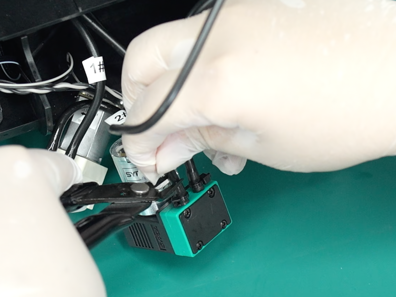
Cut the two tubes connected to the waste ink pump at a suitable distance and plug them with rubber stoppers.
-
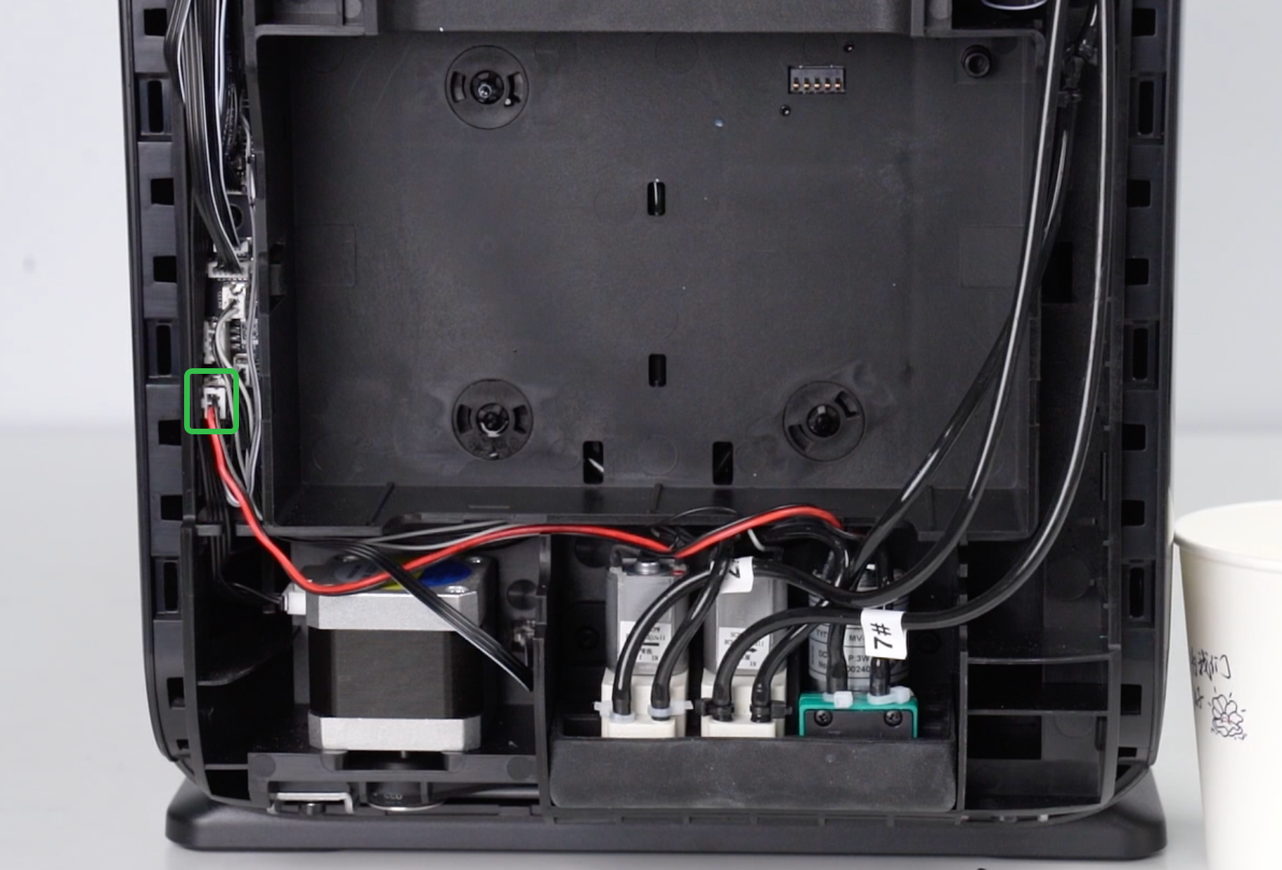
Disconnect the waste ink pump cable from the ink stack adapter board and tidy the wiring.
Step 6: Install the New Base and Waste Ink Pump
-
Take out the new waste ink pump and base.
-
Place the left and middle pumps into the new base in their original positions and tighten the corresponding screws.
-
Connect the wiring harness for the new waste ink pump in its original position, maintaining the original wiring layout.
-
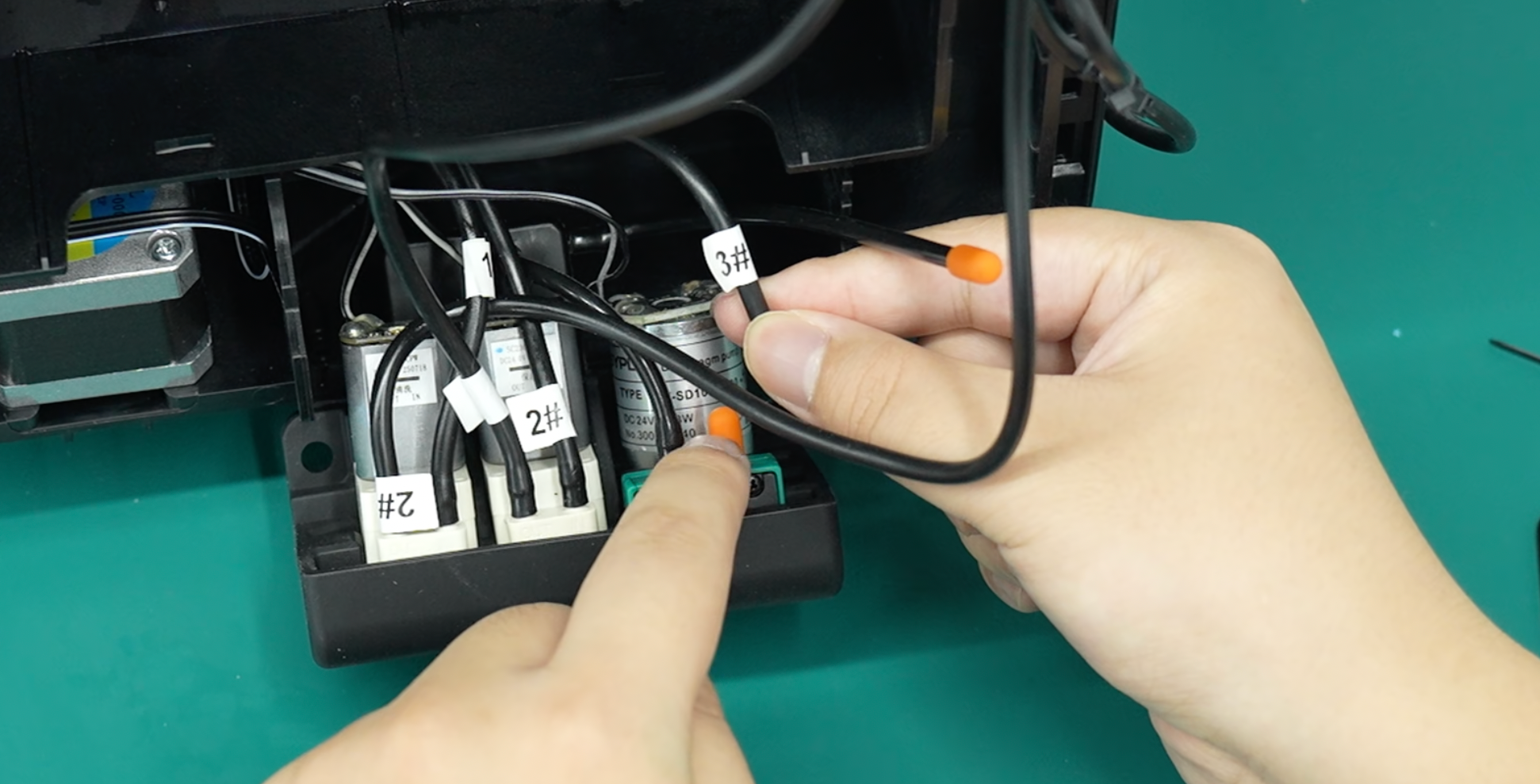
Locate the port corresponding to the tube labeled 3#, remove the stopper, and firmly push the tube into place.
-
Place the entire assembly back into position.
-
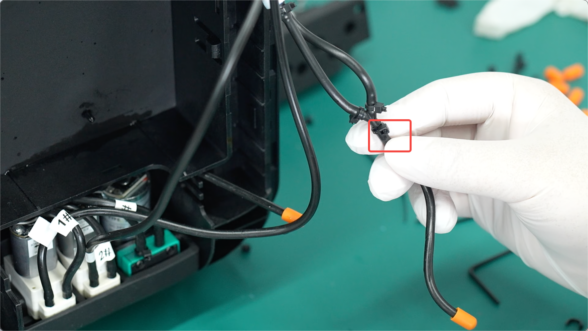
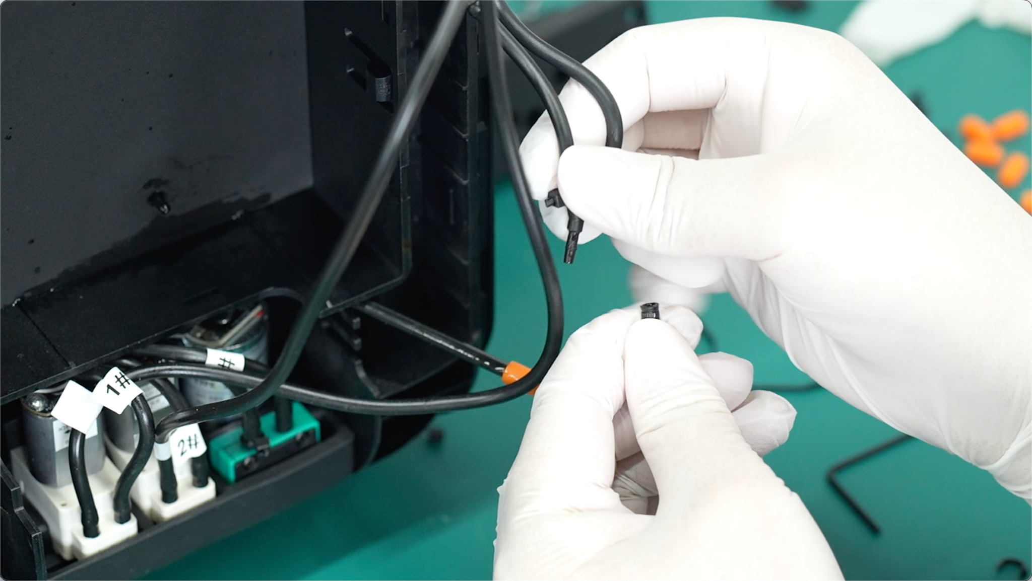
Cut the securing cable tie and pull out the indicated tube.
-
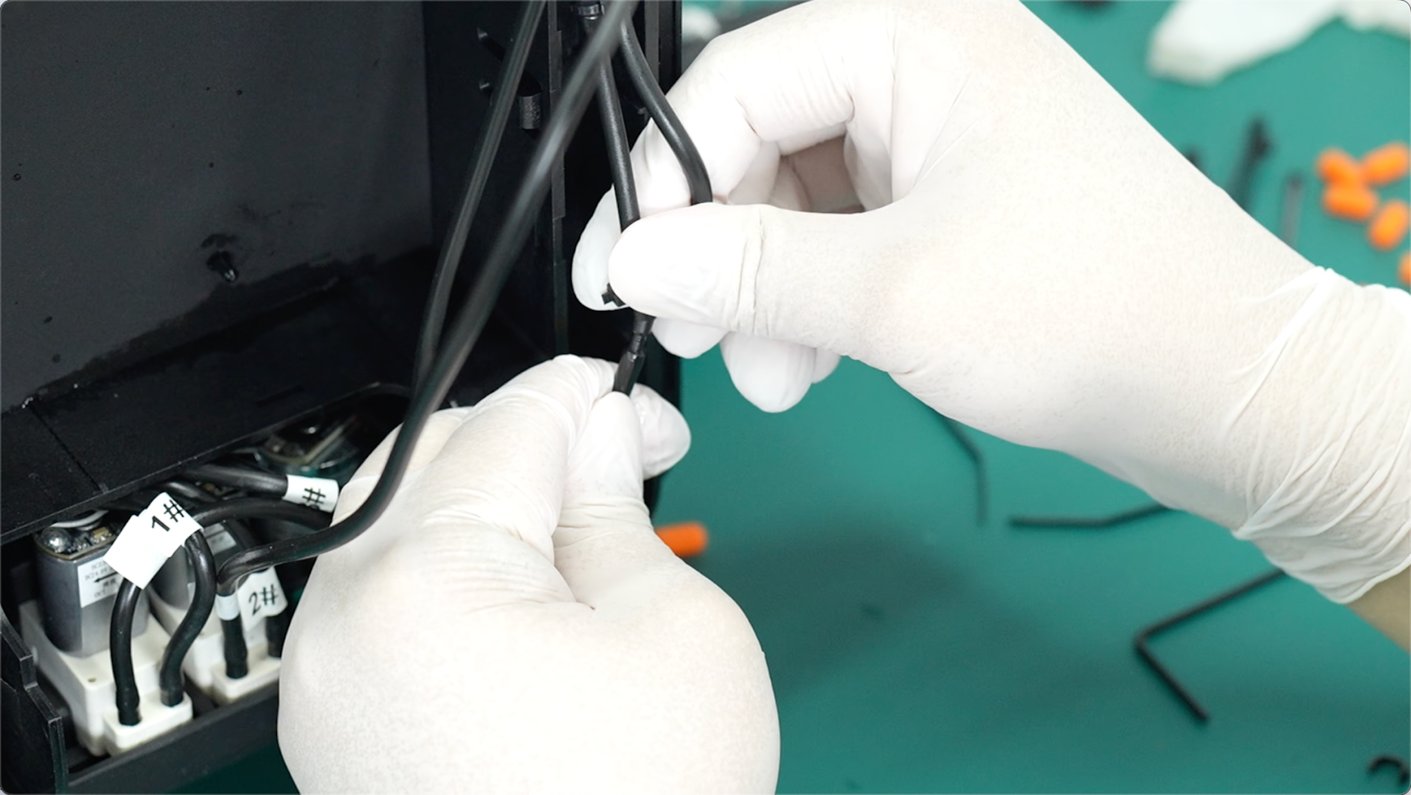
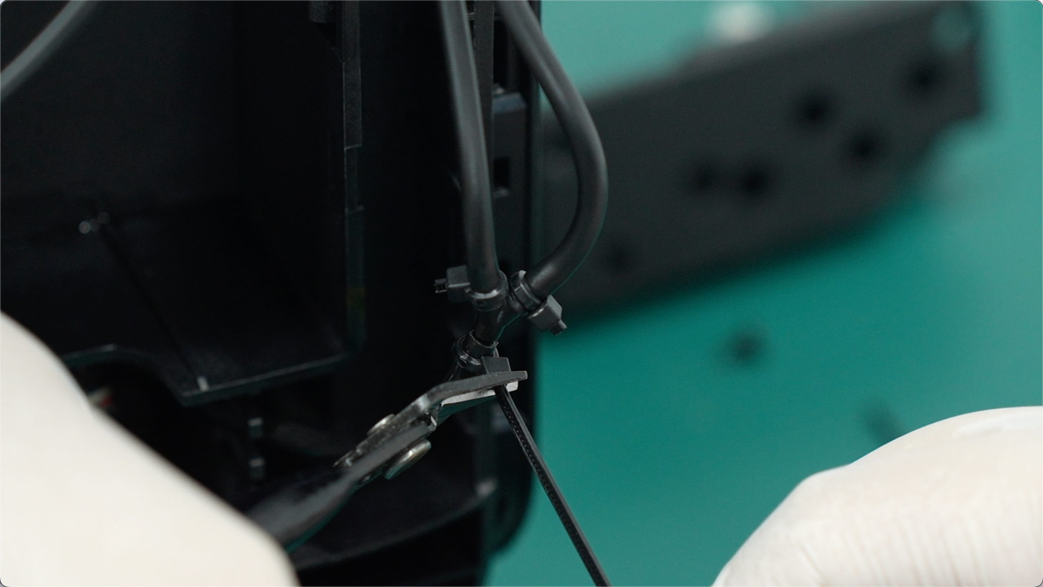
Remove the stopper, connect the tube to the port, and firmly push it into place. Take a cable tie from the tool kit, secure it tightly around the connection, and cut off the excess.
-
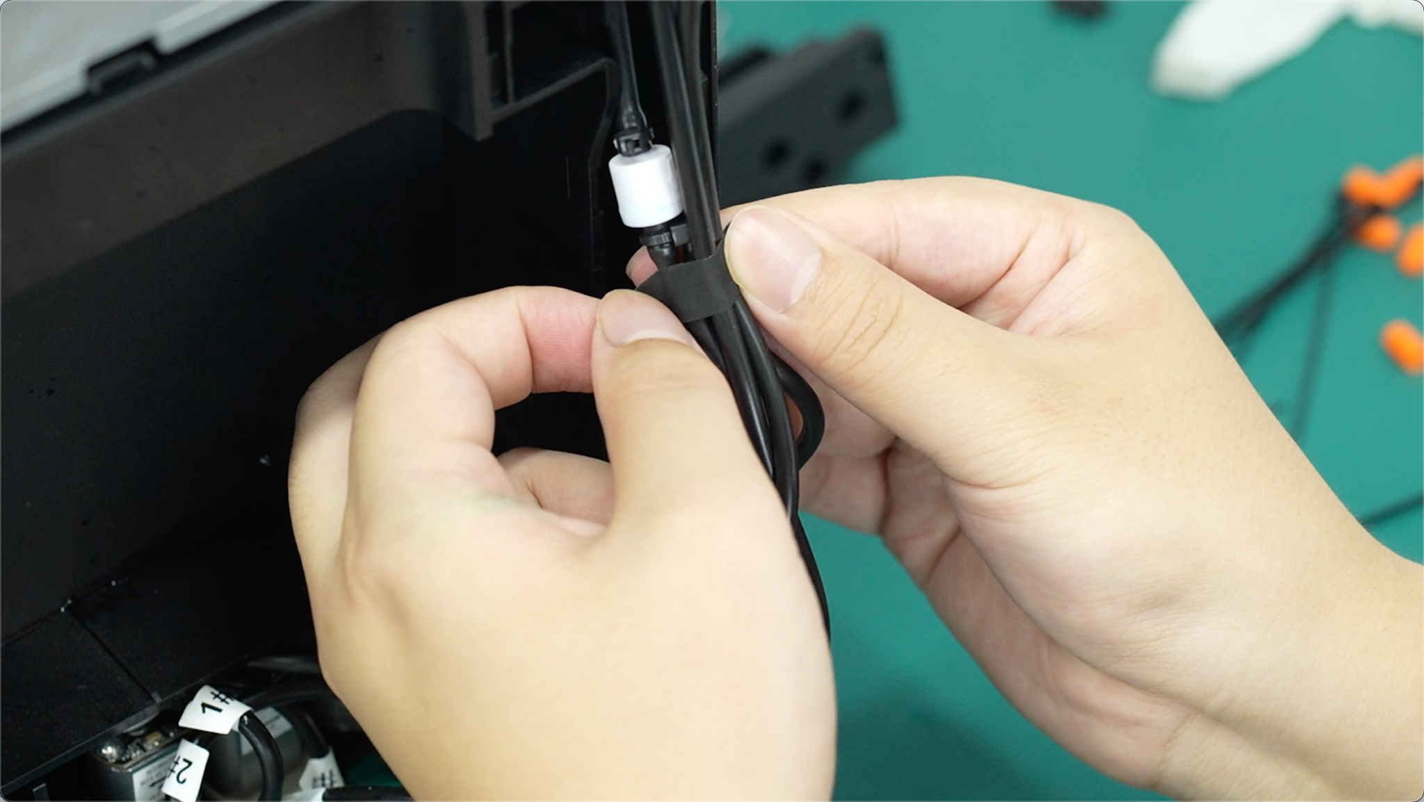
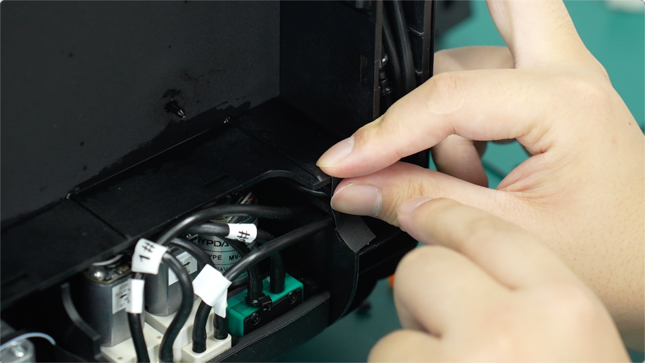
Restore the original wiring layout and secure it using the original tape.
-
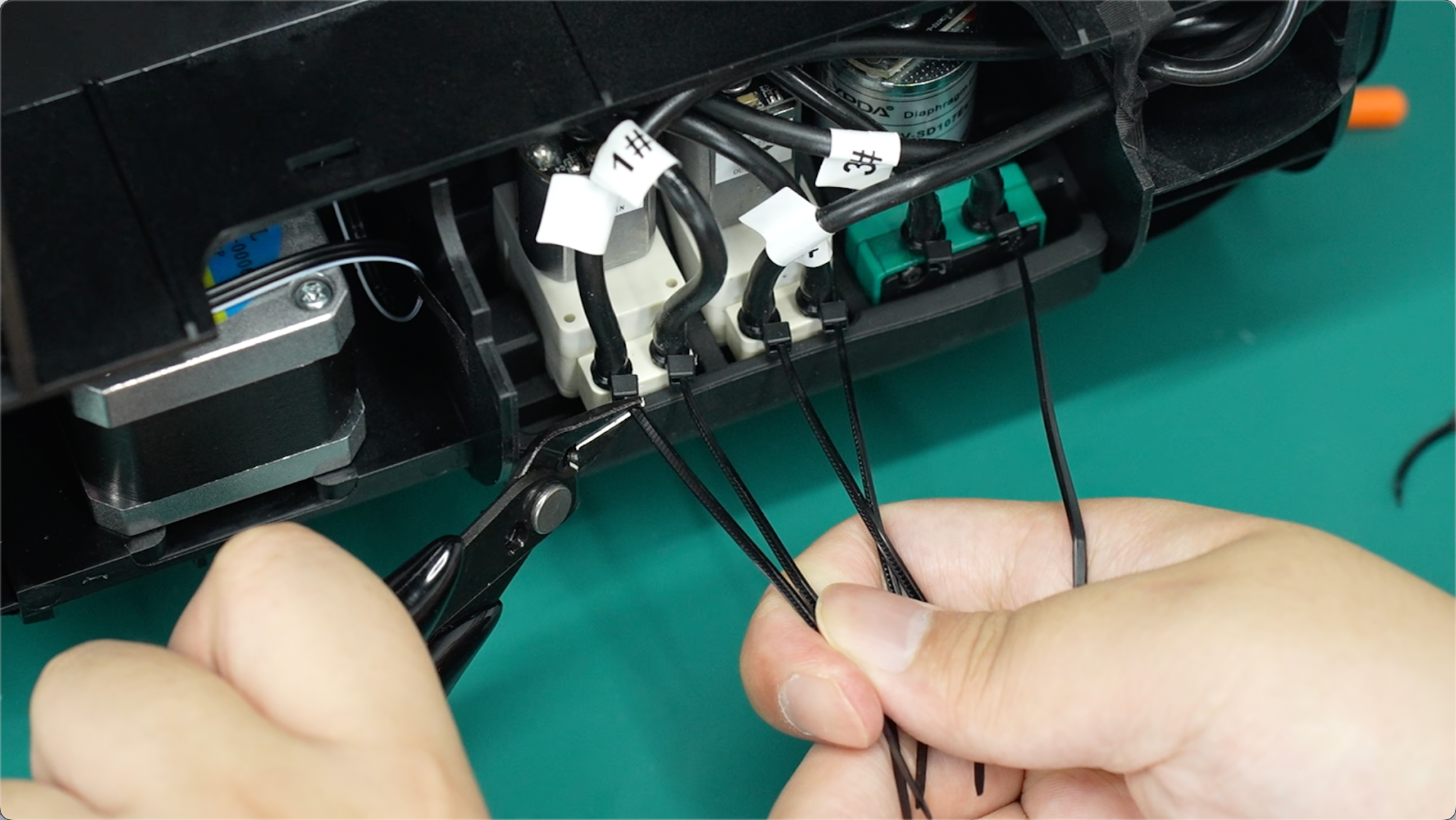
Take a cable tie, secure it tightly around the connection on the pump, and cut off the excess.
Step 7: Reinstall the Pump Mounting Bracket Assembly
-
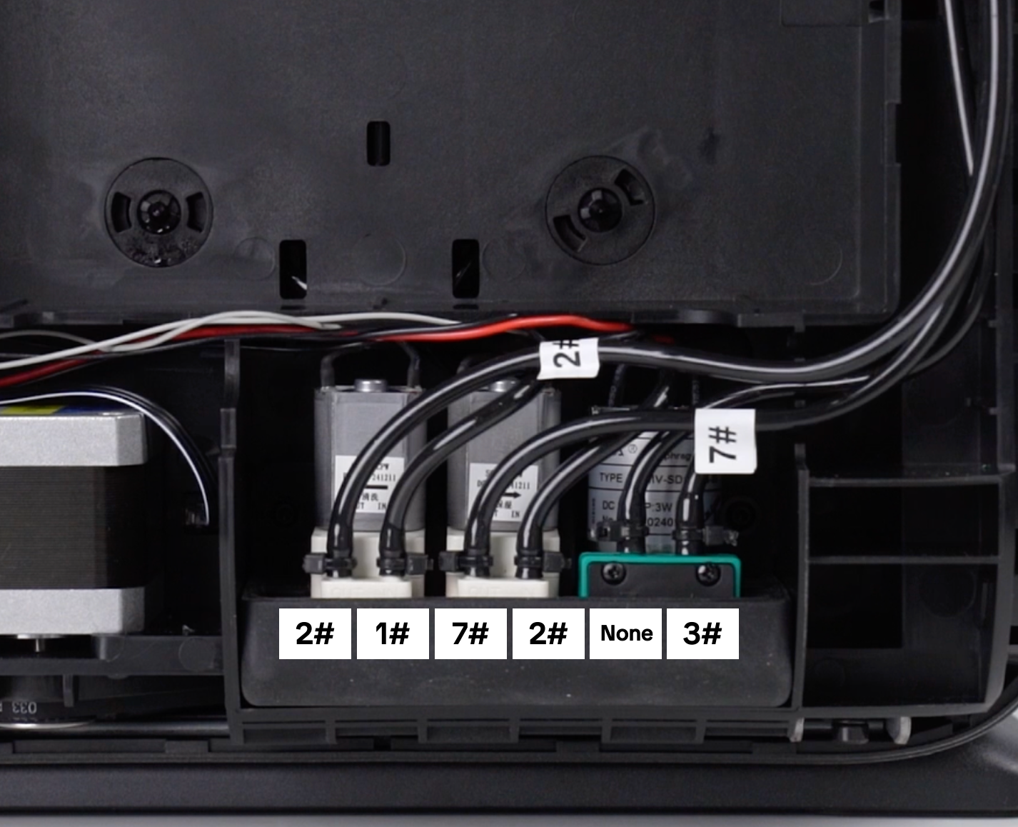
Check that the ink tubes are connected according to the correct number labels.
-
Reinstall the pump module and tighten the two screws using the 2.0 mm hex screwdriver.
-
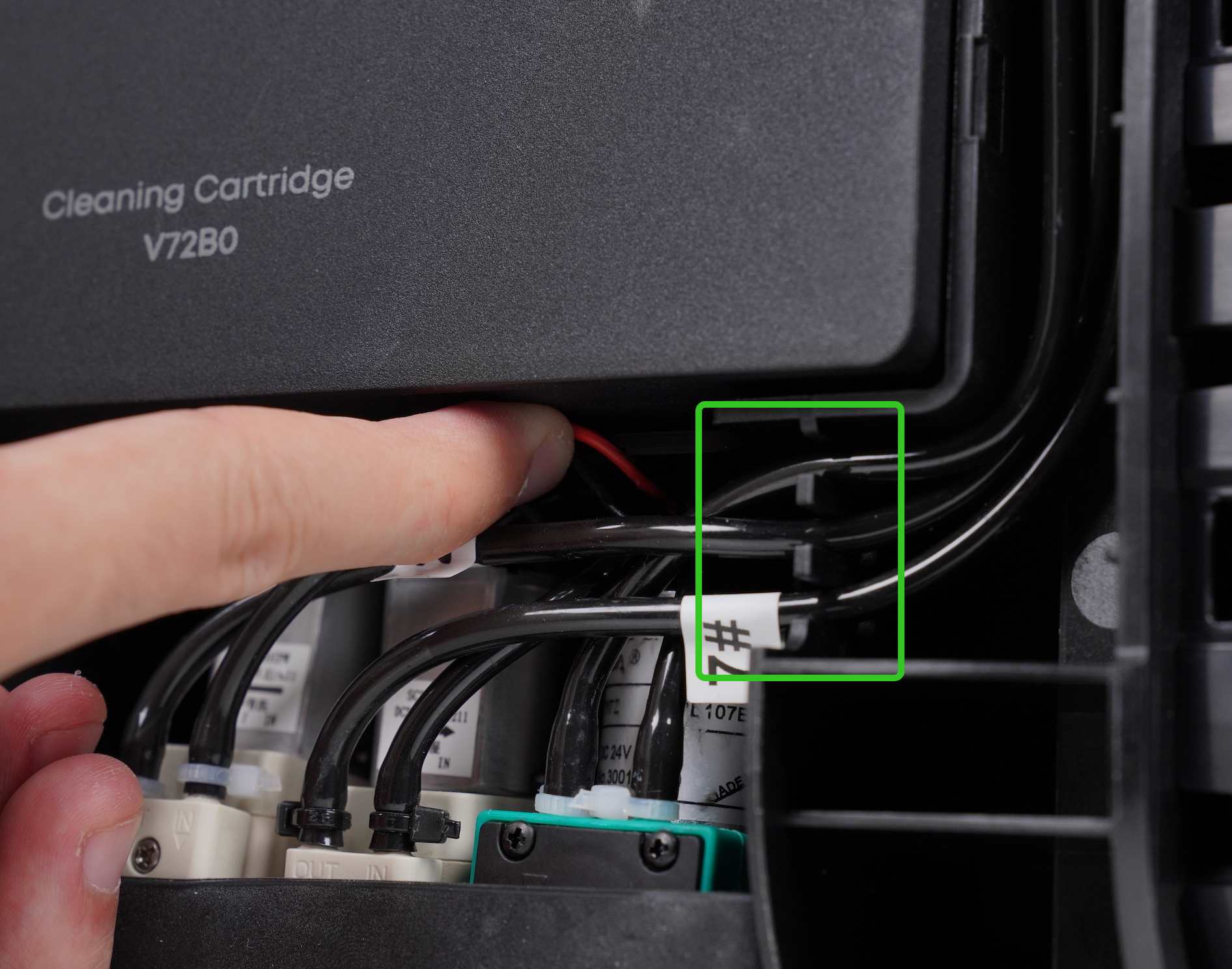
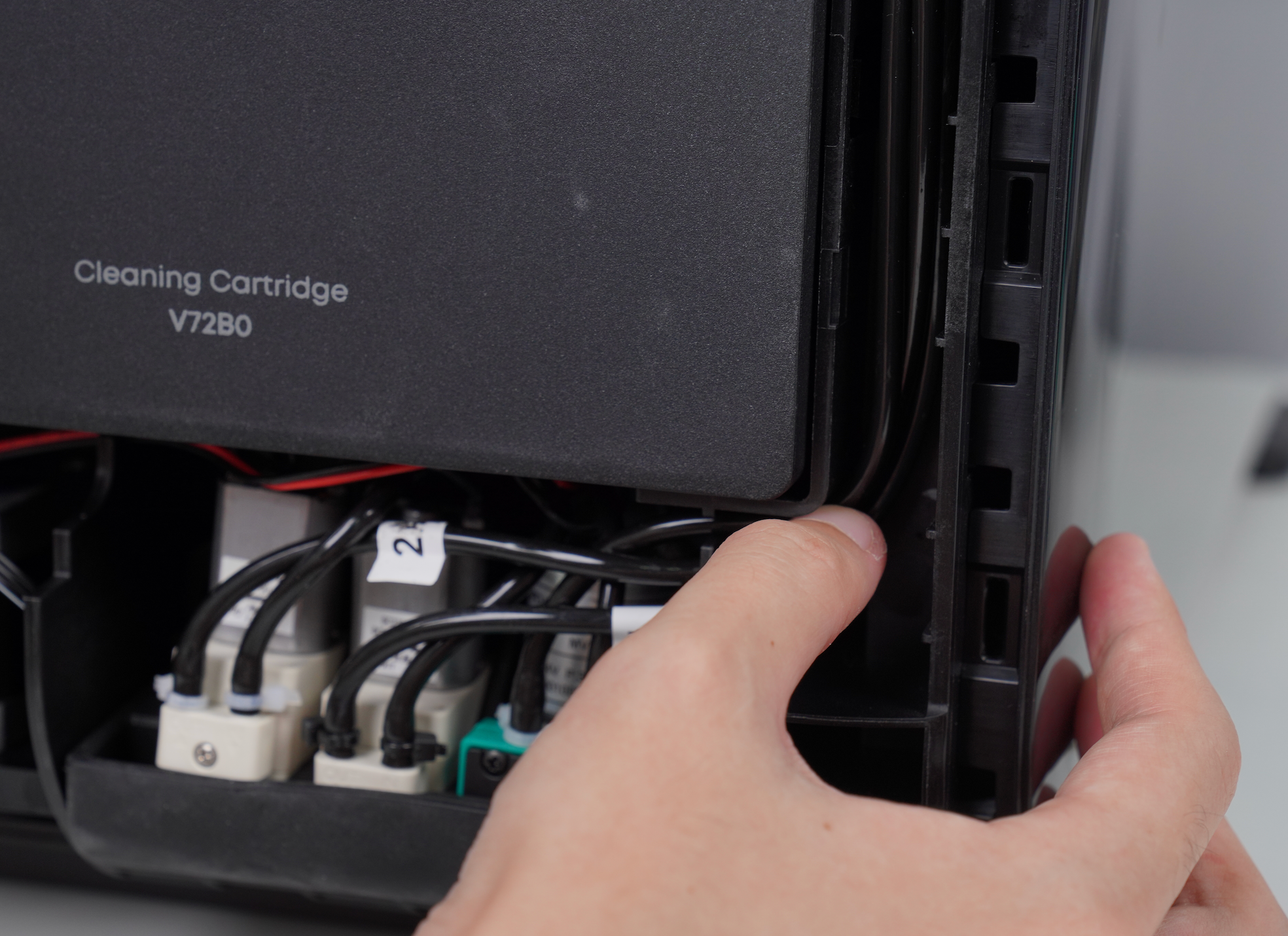
Tidy the wiring and ink tubes, then press the ink tubes back into their grooves.
Step 8: Power On the Machine
After confirming that all ink tubes and wiring are properly seated, check that no wires or hoses are exposed or pinched.
Reinstall the right-side cover and press around the edges to make sure all clips are fully seated.
After confirming that everything is installed correctly, reconnect the machine to power.