Right shell, right quick-release panel
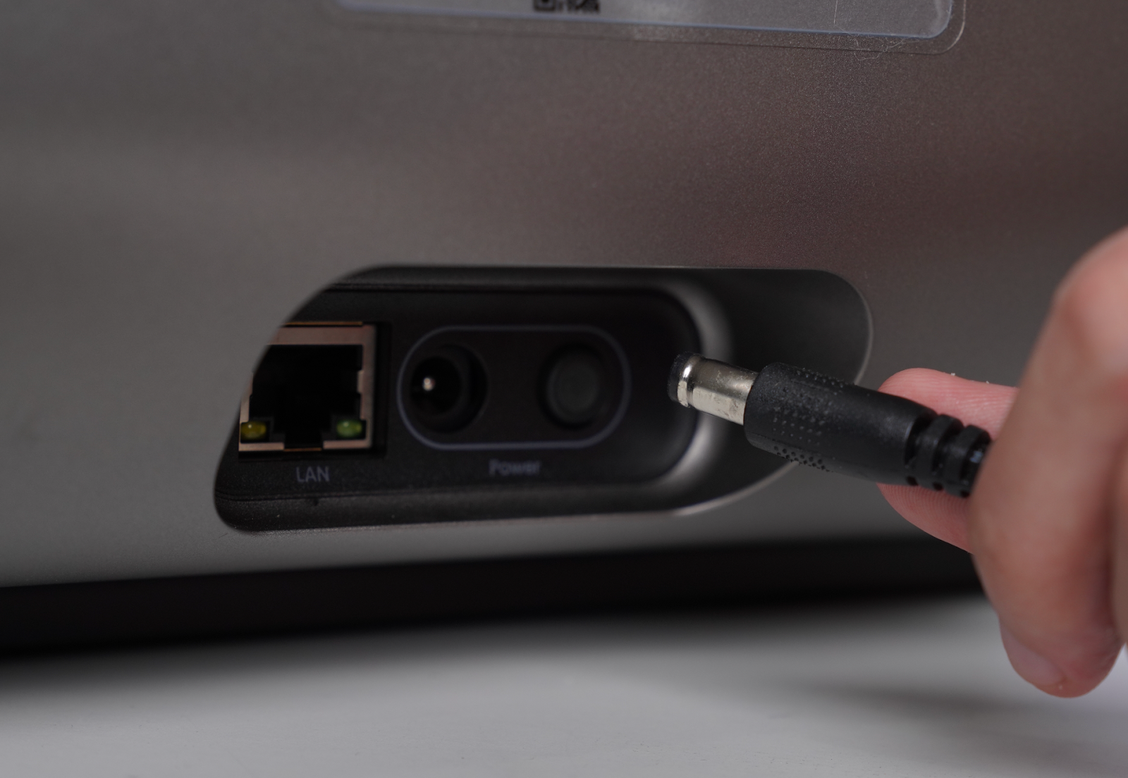
Step 1 - Power off the device and unplug the power cord
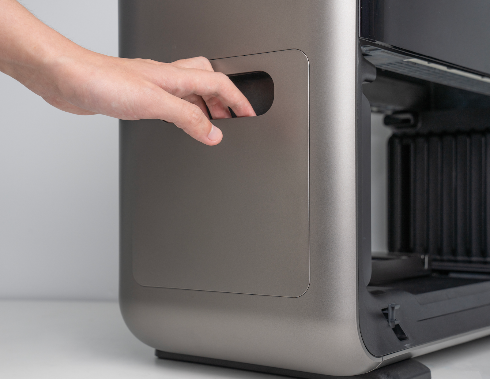
Step 2 - Remove the right quick-release panel
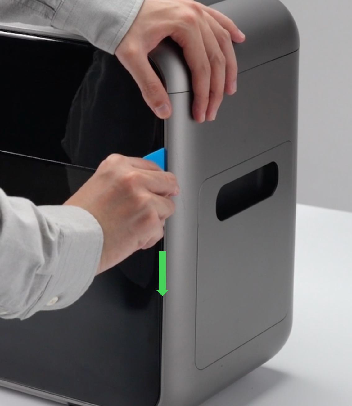
Step 3 - Remove the right side shell
Step 4 - Remove the left side shell
Step 5 - Remove the upper shell
Step 6 - Install the upper shell
Step 7 - Install the left side shell
Step 8 - Install the right side shell
Step 9 - Install the right quick-release panel
Step 10 - Reconnect the power supply
Accessory Introduction
Left shell
Right shell, right quick-release panel
Upper shell
Required Tools(Self-provided)
-
Disassembly Pry Tool / Hard Card
Safety Precautions
-
Before disassembling or installing the left side shell, always unplug the power cord. The power socket is located on the left side shell, and failure to disconnect power may damage the socket.
-
When removing the upper shell, do not open it too far. Excessive movement may pull or damage the cable connecting the upper shell keypad to the mainboard.
-
Before reinstalling the shell, ensure that the keypad cable is properly connected to the mainboard. When installing the left and right side shells, check carefully for exposed wires or ink tubes.
-
After installation, confirm that all snap-fit buckles are fully engaged and securely fastened.
-
Before removing the upper shell, the left and right side shells must be removed first.
Replacement Steps
Step 1 - Power off the device and unplug the power cord
Turn off the device and unplug the power cord.
⚠️ When removing the left side shell, make sure the power cord is disconnected, as the power socket is integrated into the left shell.
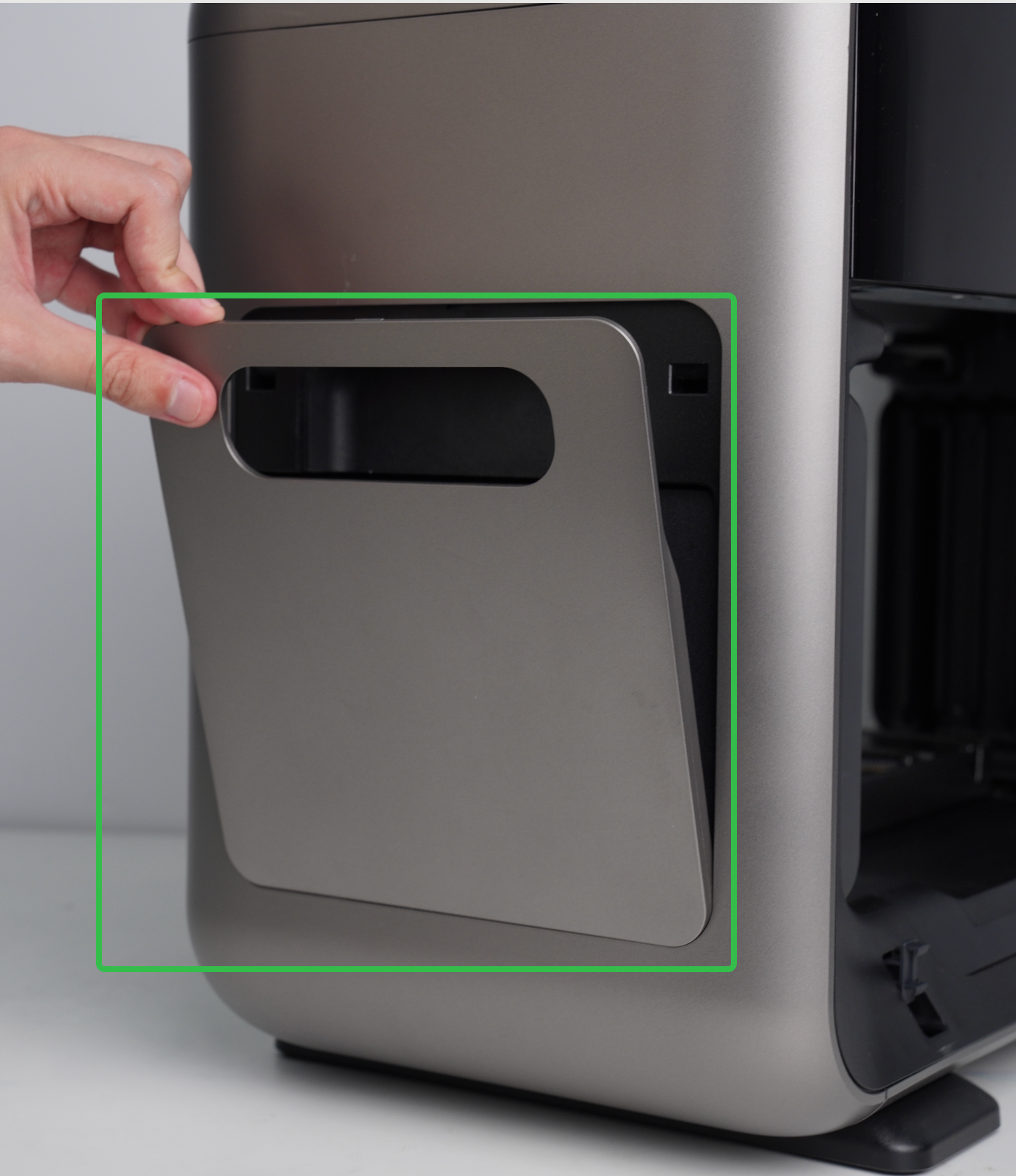
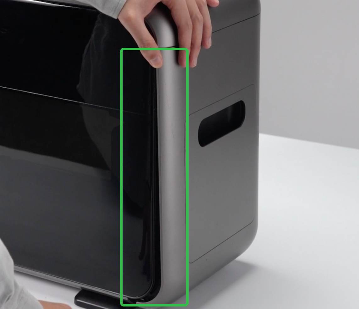
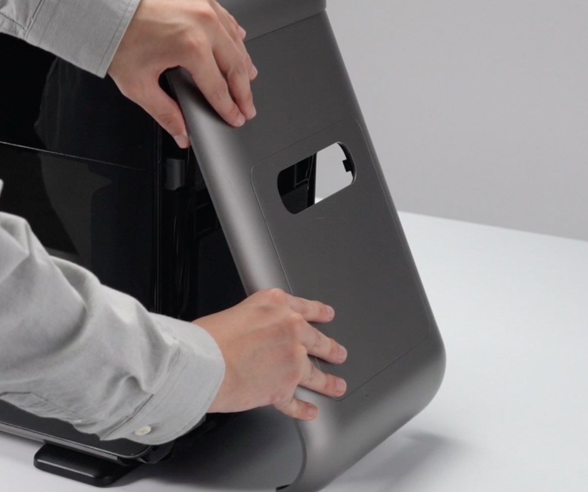
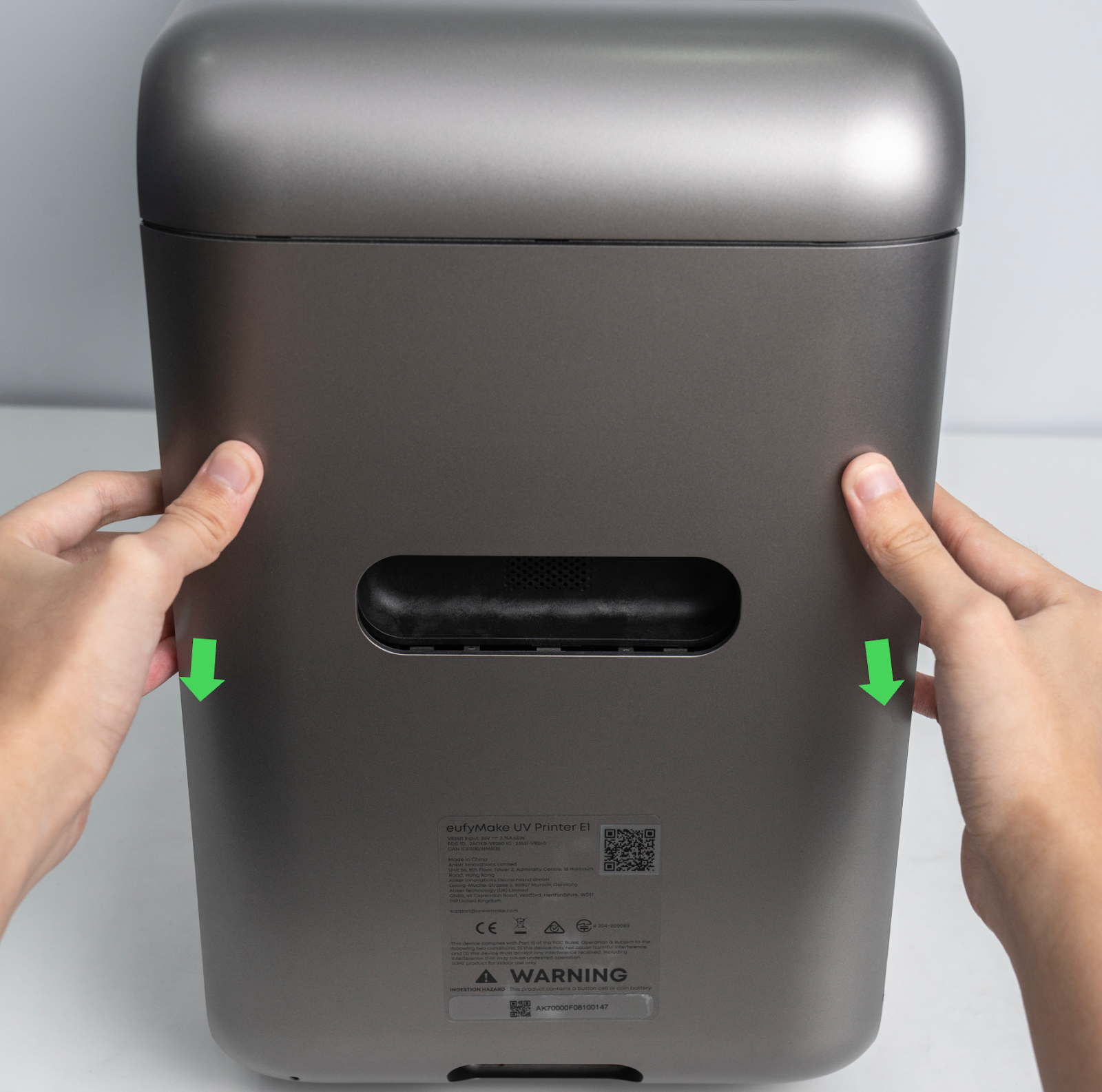
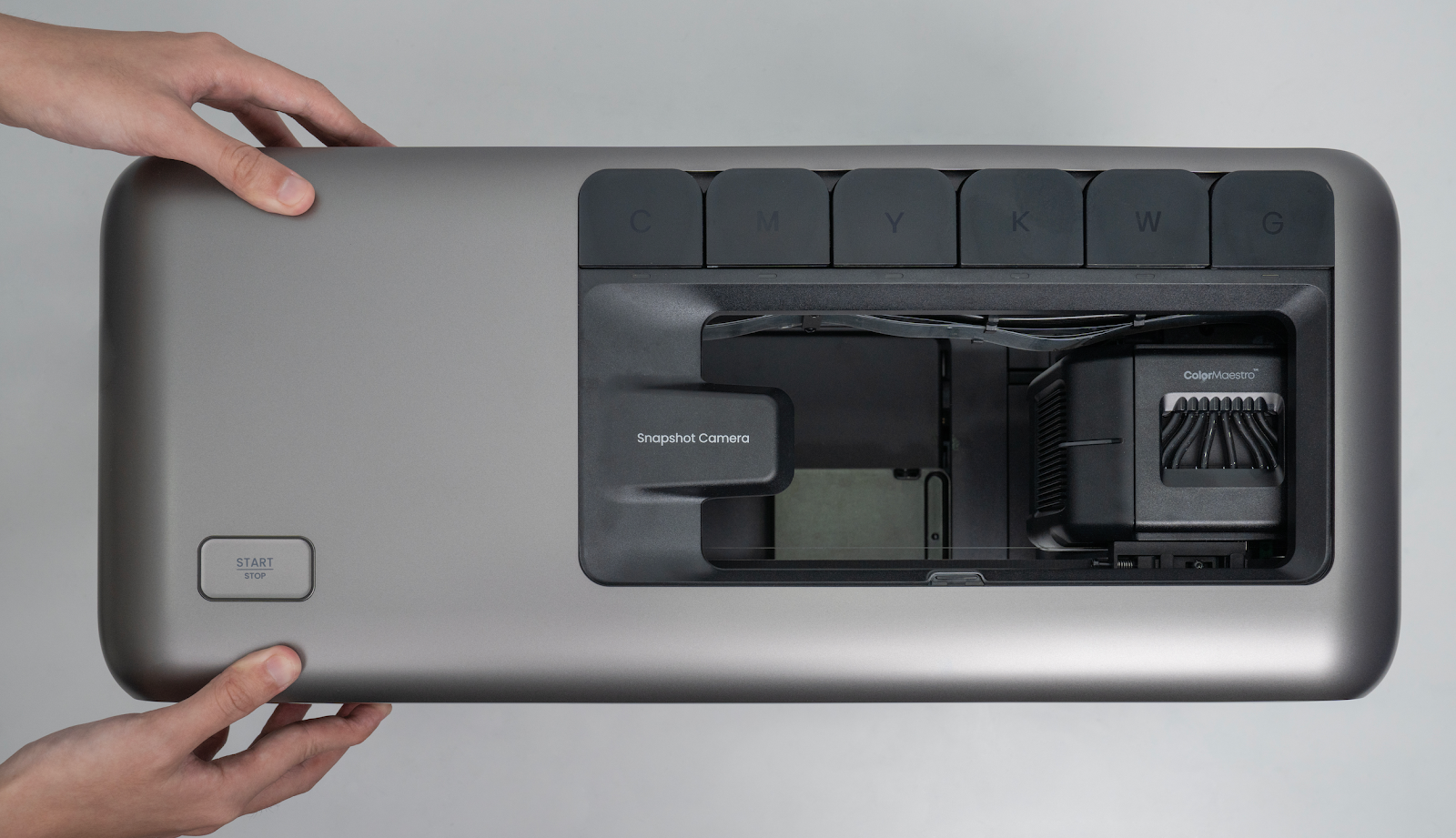
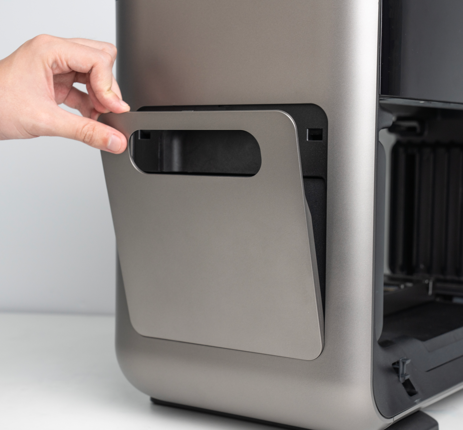
Step 2 - Remove the right quick-release panel
Grip the bottom edge on the handle of the quick-release panel and gently pry outward to remove the right quick-release panel.
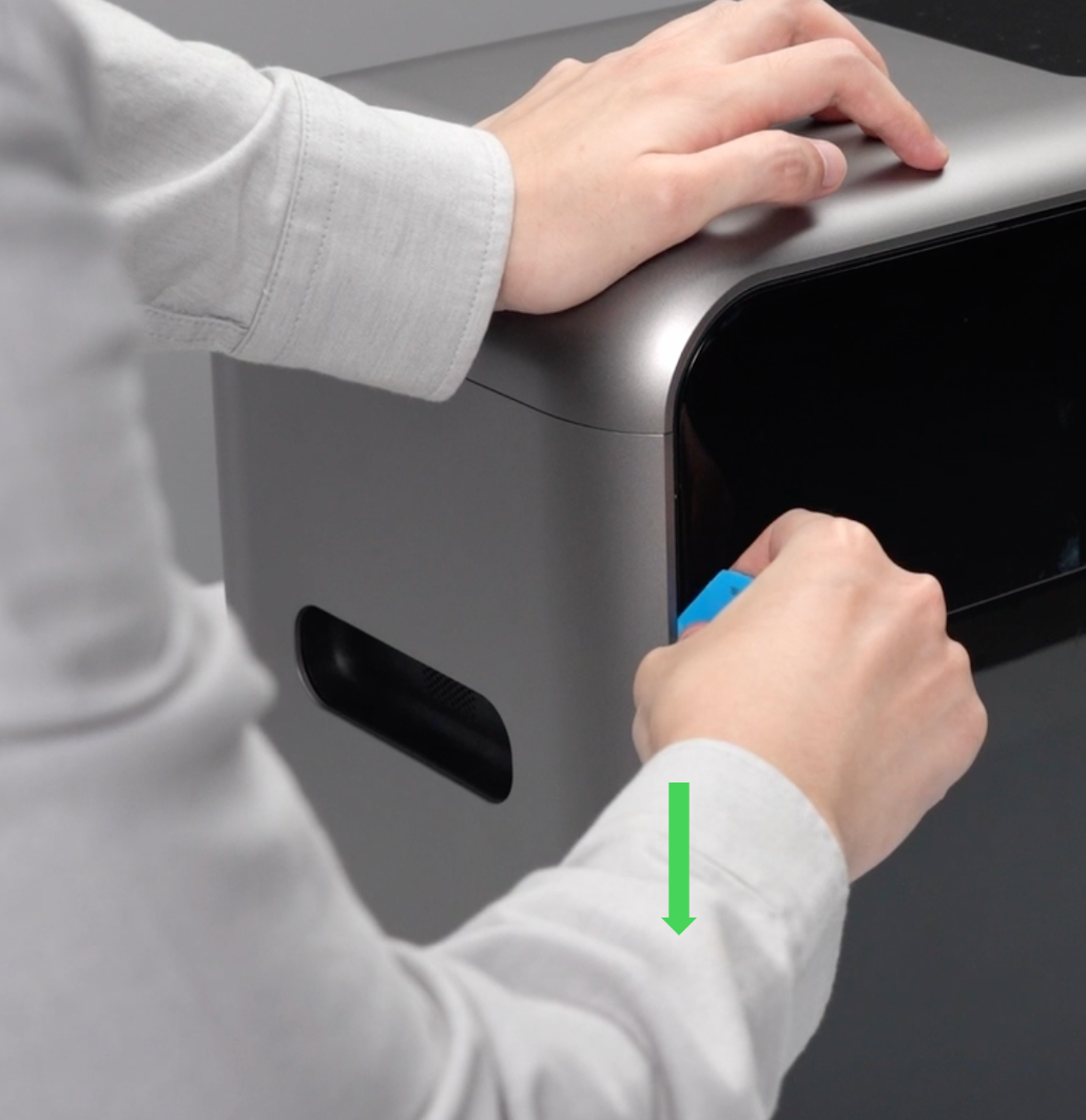
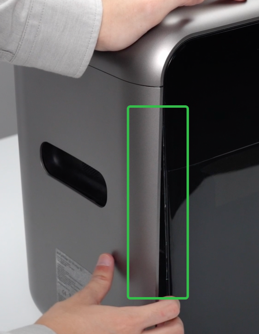
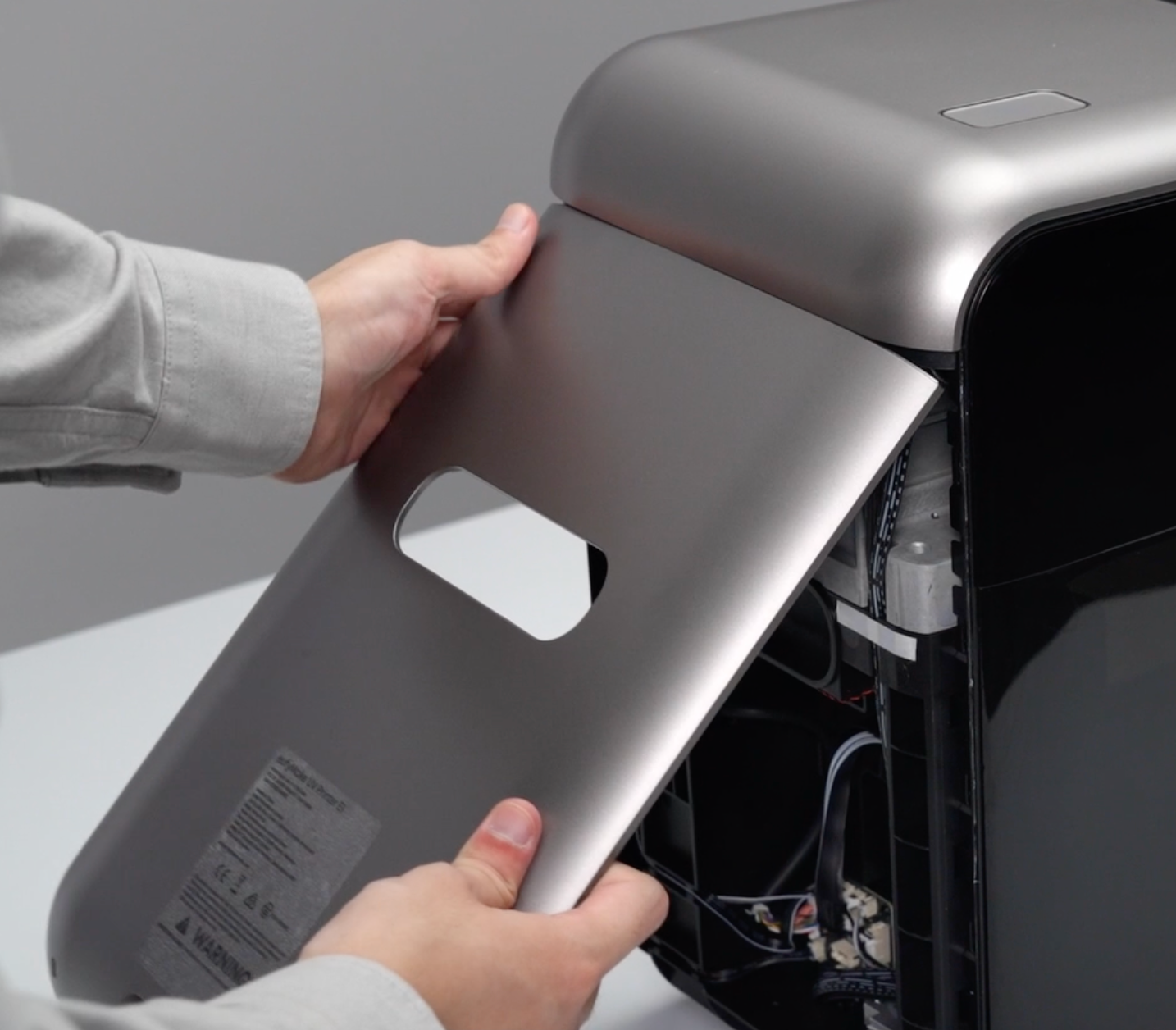
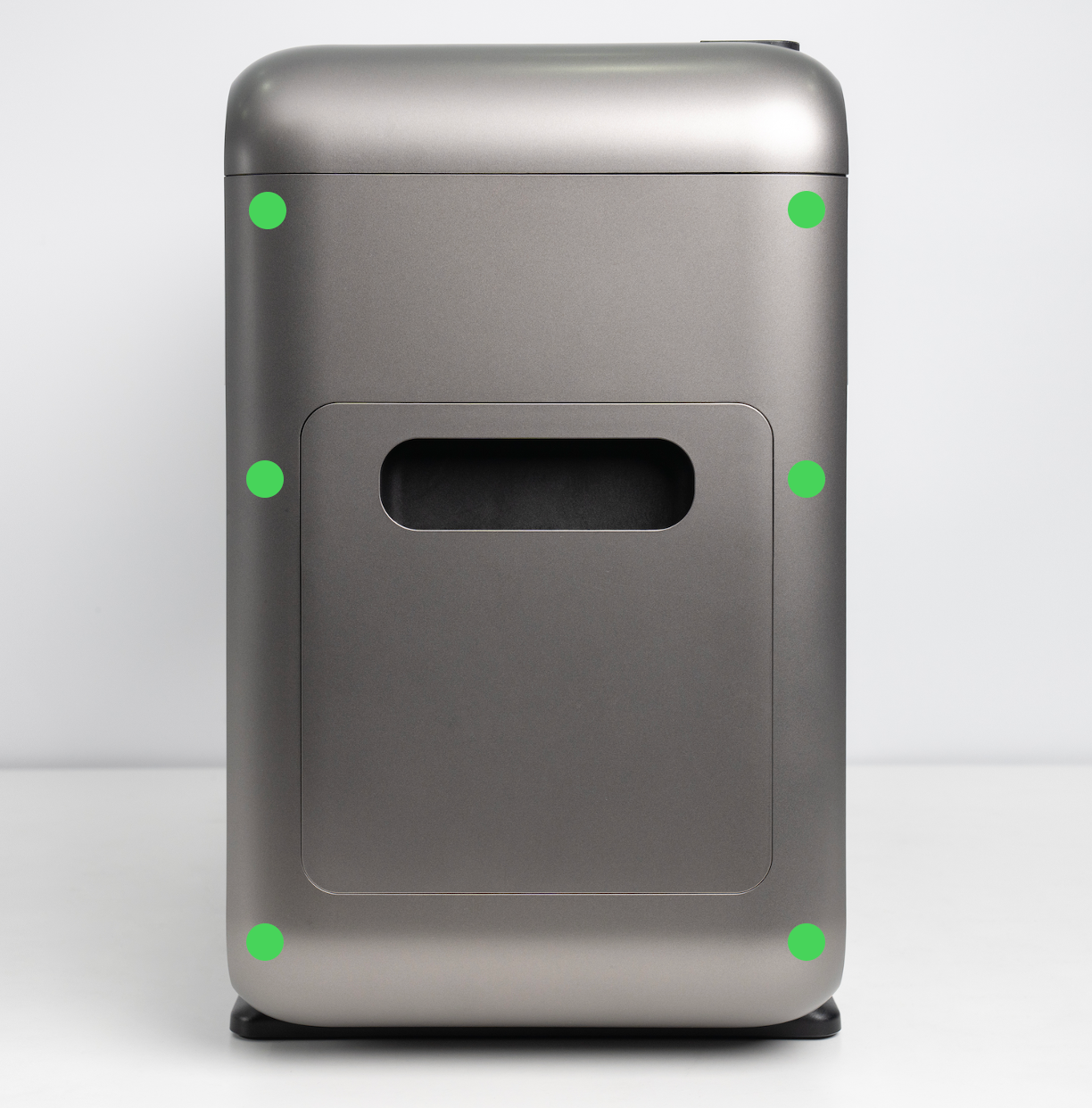
Step 3 - Remove the right side shell
-
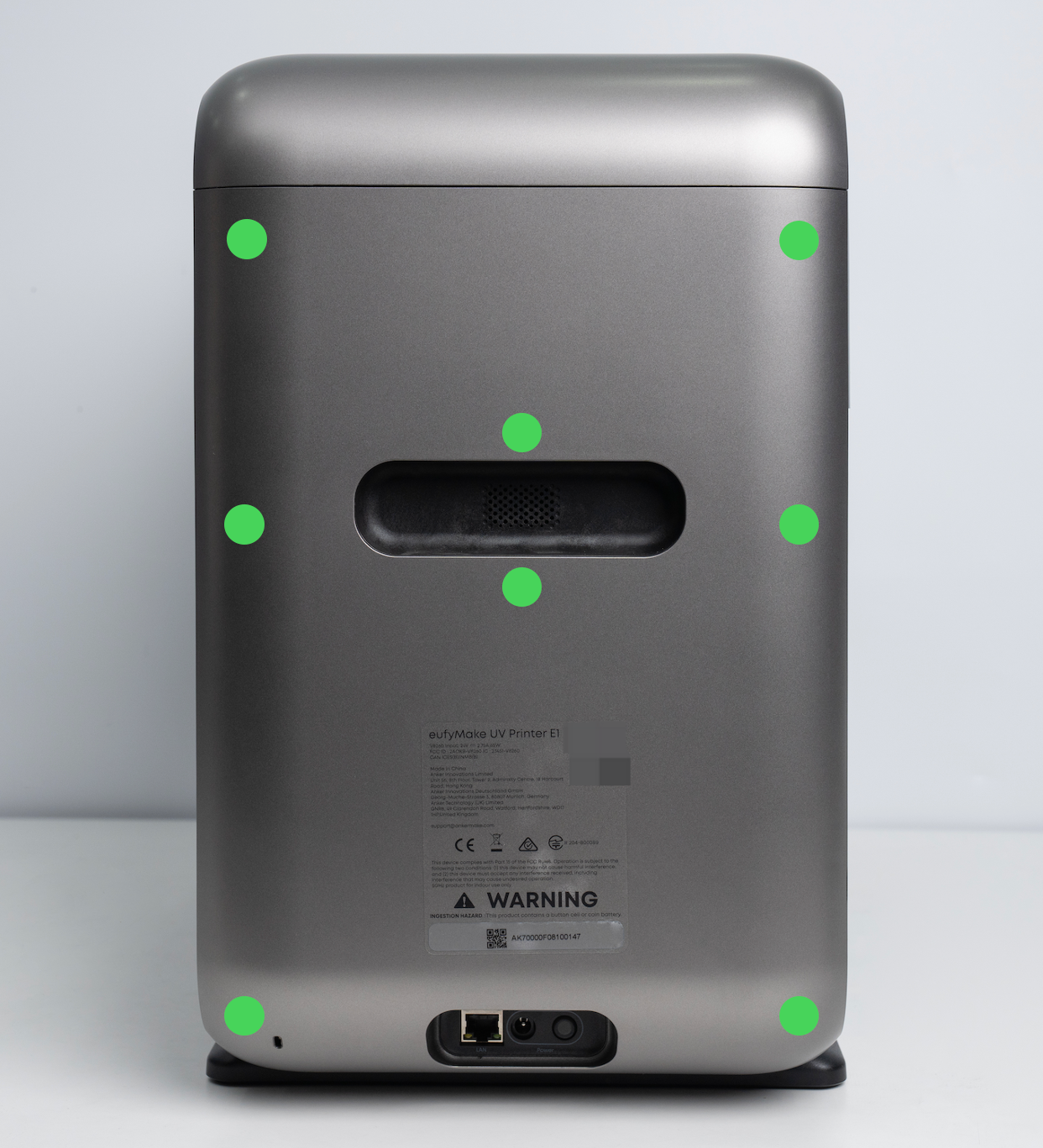
Use a pry tool to pry open a gap along the left and right edges of the shell.
-
Pull the shell outward from the bottom. The snap-fit buckles will disengage, allowing the right side shell to be removed.
Step 4 - Remove the left side shell
-
Using the same method as for the right side shell, pry open a gap along the edges of the housing with a pry tool.
-
Pull the shell outward from the bottom until the snap-fit buckles disengage, then remove the left side shell.
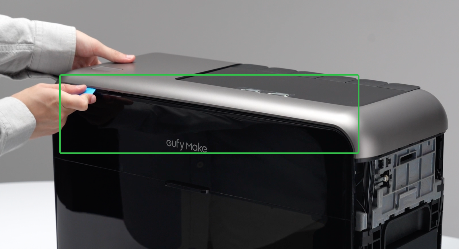
Step 5 - Remove the upper shell
-
Use a pry tool to gently pry open a gap along the front and rear edges of the upper shell.
⚠️ There is a cable connection between the upper shell and the mainboard. Do not open the shell too far to avoid pulling or damaging the cable.
-
Using both hands, lift the upper shell upward along both side edges, keeping the lifting angle small.
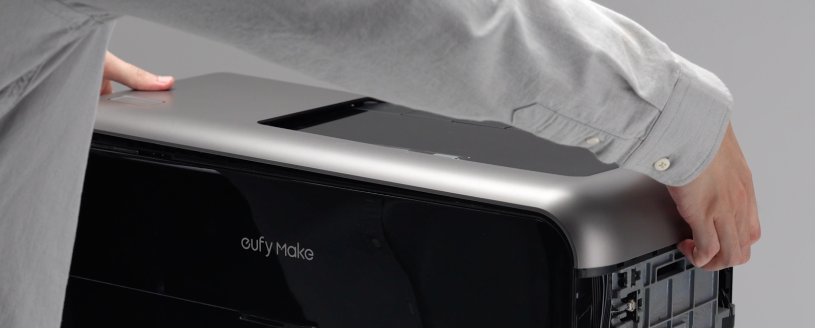
⚠️ Pay attention to the cable routing during removal.
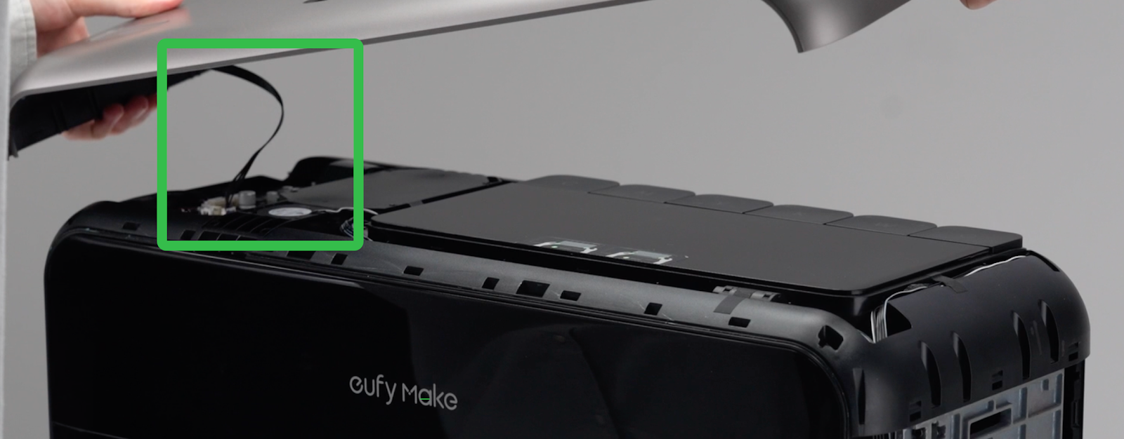
-
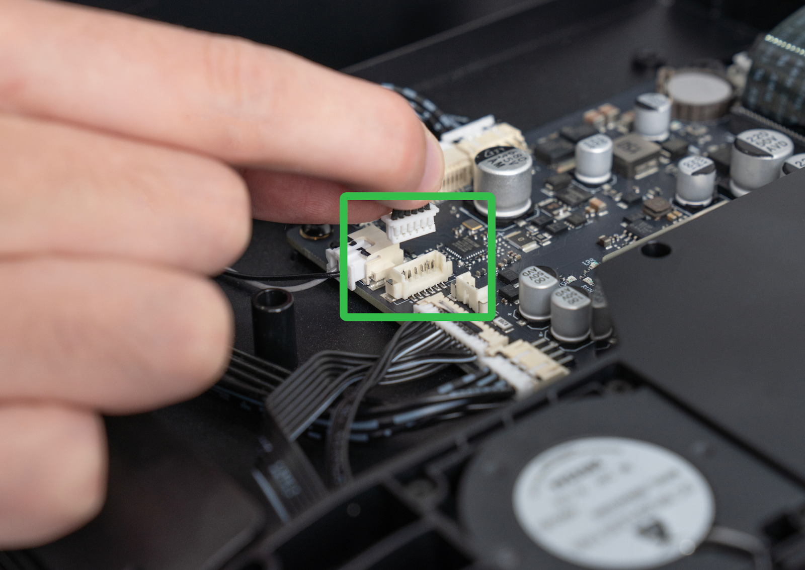
Disconnect the cable between the upper shell and the mainboard, then remove the upper shell completely.
Step 6 - Install the upper shell
-
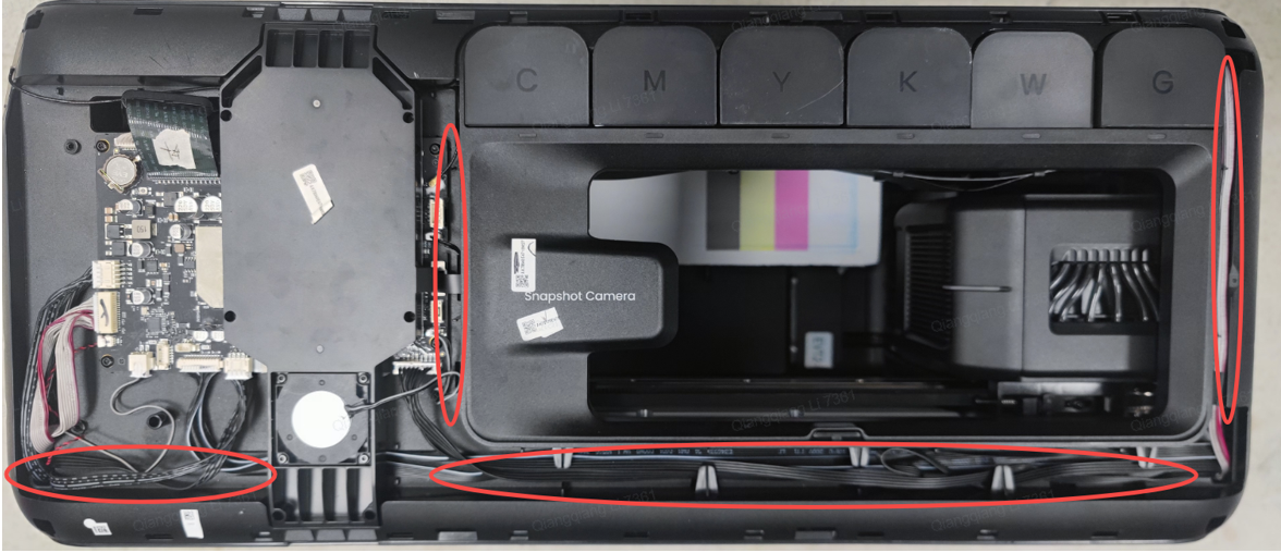
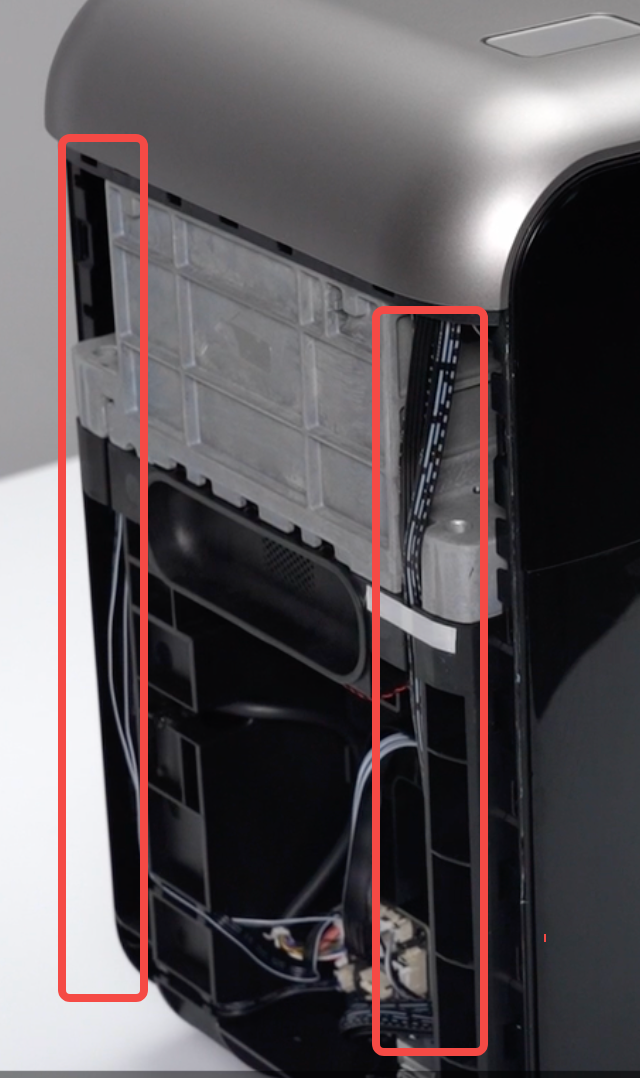
Check that the cables in the area indicated by the red box are properly routed and not protruding, to prevent pinching during installation.
-
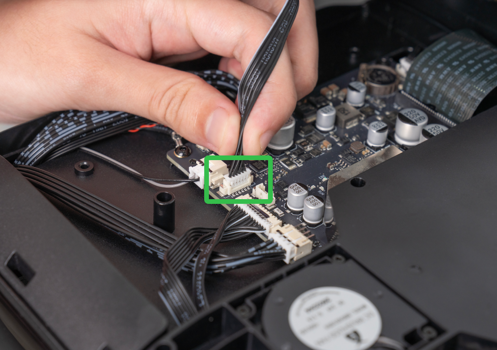
Reconnect the cable between the mainboard and the upper shell.
-
Reinstall the upper shell and press around the edges to engage all snap-fit buckles. Inspect the perimeter to ensure there are no large gaps, completing the upper shell installation.
Step 7 - Install the left side shell
-
Check that the cables in the marked area are correctly seated in the cable channels to prevent pinching.
-
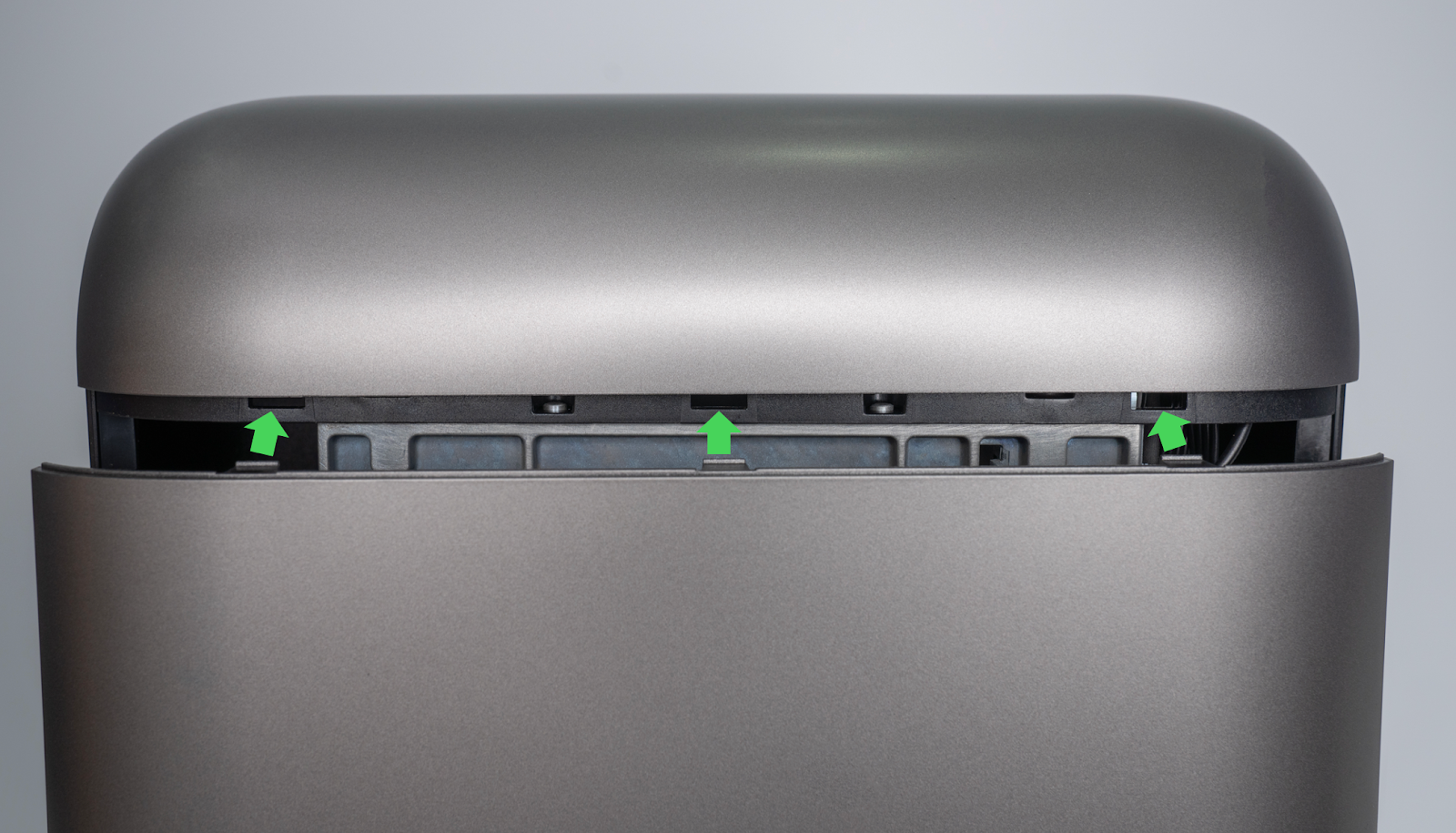
Insert the upper buckle of the left side shell into the top buckle slot.
-
Press along the marked buckle areas until a “click” is heard. Continue pressing each buckle in sequence until the shell is fully secured.
Step 8 - Install the right side shell
-
Check that the wires and ink tubes in the marked area are properly routed inside the grooves.
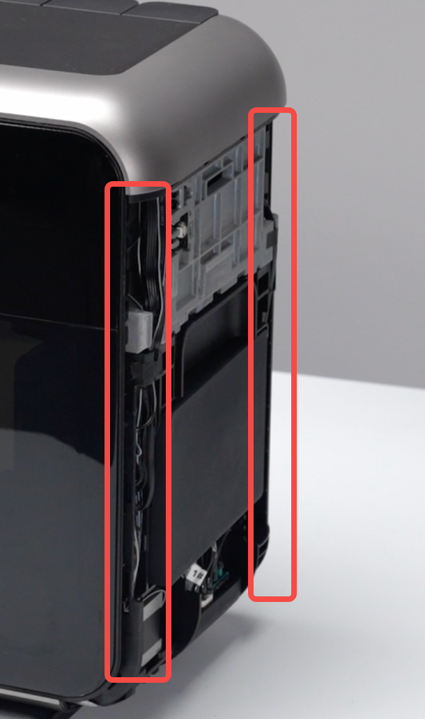
-
Insert the upper buckle of the right side shell into the top buckle slot.
-
Press along the shell edges until a “click” is heard, confirming proper engagement. Continue until all snap-fit points are secured.
Step 9 - Install the right quick-release panel
Insert the bottom edge of the quick-release panel into the left housing first, then press the top into place. Press around the panel to confirm that all clips are securely fastened.
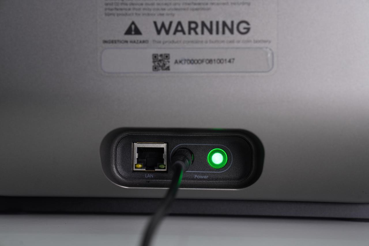
Step 10 - Reconnect the power supply
Inspect all shells to confirm that the buckles are fully engaged and that there are no gaps or bulging areas. If any gaps are present, apply firm pressure to reseat the buckles. Once confirmed, plug in the power cord.