When do I need to replace the Type-C cable?
- When the Type-C cable has poor contact, which can lead to abnormal nozzle temperatures and other issues.
- When the Type-C cable is physically damaged, which can lead to the extruder failing to function properly and other issues.
How do I replace the Type-C cable?
1. Power off the M5 printer. Carefully lay the printer on its side, remove the bottom base cover, unplug the Z-axis motor wires, and then use an H2.0 hexagonal wrench to loosen the four Type-C cable terminal screws and unplug both Type-C cables.


2. Use an H4.0 hexagonal wrench to loosen the eight gantry screws and separate the gantry from the base.

3. Use an H2.0 hexagonal wrench to remove the four motor base screws of the Z-axis left and right profiles.


4. Carefully remove the Z-axis left and right motors, separate the Type-C cable and the motor seat, and then remove the Z-axis motor.


5. Use an H2.5 hexagonal wrench to remove the four material rack screws and remove the material rack, and then use an H2.0 hexagonal wrench to remove the Z-axis left and right profile upper cover screws and remove the upper covers.


6. Use an H4.0 hexagonal wrench to remove the four beam screws and remove the beam, and then use an H2.0 hexagonal wrench to remove the eight Z-axis profile upper cover screws and remove the Z-axis left and right profile upper covers.


7. Remove the left and right Z-axis profiles.

8. Remove the left Type-C cable.
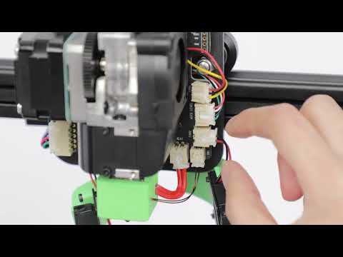
8.1 Remove the two nozzle Type-C cable terminal screws with an H2.0 hexagonal wrench and remove the Type-C cable.

8.2 Remove the three screws on the left shoulder housing with an H2.0 hexagonal wrench.


8.3 Remove the two Type-C cables and Z-axis left slider screws with an H2.0 hexagonal wrench.

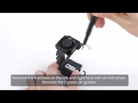
8.4 Carefully pull the left shoulder shell cover upward and unplug the break-detection switch wire. Use an H1.5 hexagonal wrench to remove the two break-detection seat screws, and then use an H2.0 hexagonal wrench to remove the three left key shell base screws.


8.5 Carefully remove the Type-C cable.


9. Install the left Type-C cable.
9.1 Install a new Type-C cable on the Z-axis left slider, and then use an H2.0 hexagonal wrench to tighten the two screws.


9.2 Use an H2.0 hexagonal wrench to tighten the three screws to lock the left key shell base to the Z-axis left slider block, and then use an H1.5 hexagonal wrench to tighten the two screws to install the break-detection switch to the left hanger base. Carefully plug in the break-detection switch wire, connect the Type-C cable, install the left shoulder shell cover, and then tighten the three left shoulder shell screws with an H2.0 hexagonal wrench.


9.3 Insert the nozzle Type-C cable and tighten the two nozzle Type-C cable terminal screws with an H2.0 hexagonal wrench.

10. Remove the right Type-C cable.
10.1 Invert the X-axis assembly and remove the right Type-C cable screw with an H2.0 hexagonal wrench.


10.2 Remove the seven right shoulder pendant screws with an H2.0 hexagonal wrench, and then remove the right shoulder pendant back cover.


10.3 Remove the right shoulder rear housing cover, and then use an H2.0 hexagonal wrench to remove the five screws that lock the right shoulder front housing.


10.4 Use an H2.0 hexagonal wrench to remove the two motor synchronous wheel housing screws, ground wire connecting screws, two Type-C cable screws, and then carefully unplug the Type-C cable.


10.5 Remove the front cover of the display screen, remove the display screen cover, unplug the camera LED light wire, push the buckle forward to remove the camera cable, unplug the X-axis motor wire and push up the FCC cable buckle to unplug the FCC cable, and then remove the entire display screen module.


10.6 Use an H2.5 hexagonal wrench to remove the two right shoulder hanger and Z-axis slider screws, and then remove the Z-axis right slider.


10.7 Separate the right pendant back cover and bracket, and then thread the Type-C cable through the bracket and back cover.


11. Install the right Type-C cable.
11.1 Install a new Type-C cable on the Z-axis slider, and then use an H2.0 hexagonal wrench to tighten the two screws.


11.2 Thread the new Type-C cable through the right pendant back cover and bracket.


11.3 Use an H2.5 hexagonal wrench to tighten the two right shoulder hanger and Z-axis slider screws.

11.4 Use an H2.0 hexagonal wrench to tighten the four right pendant back cover screws.

11.5 Plug in the camera LED light wire, camera cable, X-axis motor wire, and the FCC cable.


11.6 Insert the new Type-C cable and use an H2.0 hexagonal wrench to install the Type-C cable screws.
11.7 Use an H2.0 hexagonal wrench to tighten the ground connection screws and install the front cover of the display screen.


11.8 Install the front cover and use an H2.0 hexagonal wrench to tighten the screws.


11.9 Use an H2.0 hexagonal wrench to tighten the right shoulder back cover and bottom housing screws.


12. Pass the Type-C cable through the Z-axis slider and the left and right profiles of the Z-axis.

13. Rotate the left and right motor threads back to the Z-axis left and right sliders, make sure the Type-C cable buckle is clamped to the corresponding position of the motor seat, and then use an H2.0 hexagonal wrench to tighten the four motor seat screws.


14. Use an H2.0 hexagonal wrench to tighten the eight Z-axis profile upper cover plate screws, and then use an H4.0 hexagonal wrench to tighten the four beam screws.


15. Use an H2.0 hexagonal wrench to tighten the left and right upper cover screws of the Z-axis profile, and then install the material rack and use an H2.5 hexagonal wrench to tighten the four material rack screws.


16. Use an H4.0 hexagonal wrench to tighten the eight gantry screws.

17. Plug in the Z-axis motor wire, plug in the Type-C cable, use an H2.0 hexagonal wrench to tighten the four Type-C cable terminal screws, and then install the bottom base cover.

If you have any further questions, please contact us for assistance.