Root Cause of the Issue
1. Filament Obstruction: The blockage may be caused by the filament getting stuck inside the extruder gear.
2. Throat Tube Blockage: The blockage may occur due to the filament being stuck in the throat tube.
3. Nozzle Wear and Tear: When the nozzle has been used over an extended period of time, it may lead to the accumulation of filament residue inside the nozzle.
4. Internal Wear and Tear of the Nozzle Throat: The blockage may be caused by the internal wear and tear of the nozzle throat.
Solution
1. Filament Obstruction: If the filament cannot be extruded or retracted, it is possible that the filament is blocked inside the throat tube or the filament is stuck inside the extruder gear.
2. Nozzle Blockage: If the filament cannot be extruded but can be retracted, then it is likely that the nozzle is blocked.
Please refer to the following article and video for instructions on how to perform the "extrusion" and "retraction" operations:
- Article: How to load and retract the filament for the M5C printer
- Video: How to load and retract the filament for the M5C printer
I. Filament Blockage Inside the Extruder Gear
Uninstalling the extruder:

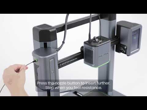
1. If the filament cannot be retracted, press the pneumatic interface on the nozzle assembly, pull out the Teflon tube, and then cut the filament with a pair of diagonal pliers (try to cut it flush with the pneumatic interface).

2. Pull up to remove the front and top covers of the extruder.

3. Use a 2.5 wrench to unscrew the extruder handle adjustment screw and open the extruder gear inspection port.


4. Use a pair of tweezers to remove the clogged filament inside the extruder gear.

Installing the extruder:
1. Use a 2.5 wrench to adjust the tightness of the extruder wrench screw.
2. Cover the front and top covers of the extruder.
3. Insert the Teflon tube into the pneumatic interface and clip the Teflon tube into the buckle on the Type-C cable.
If the above operation still cannot remove the filament inside the extruder gear, please try the following steps.
Uninstalling the extruder gear:
1. Power off the printer.
2. If the filament cannot be retracted, press the pneumatic interface on the nozzle assembly, pull out the Teflon tube, and then cut the filament with a pair of diagonal pliers (try to cut it flush with the pneumatic interface).

3. Use a 2.0 wrench to unscrew the screw for the Type-C cable and pull out the Type-C cable.

4. Pull up to remove the front and top covers of the extruder.

5. Pull out the strain gauge terminal.

6. Use a 2.0 wrench to unscrew the four screws for the extruder (two on each side), remove the extruder assembly, and then use a 2.5 wrench to unscrew the extruder handle adjustment screw.


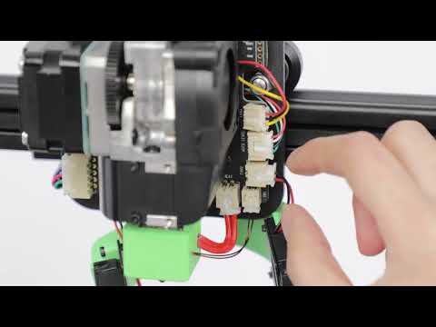
7. Unplug the heating tube, thermosensitive wire, throat tube fan, model fan, breakage detector, and extruder motor terminal.

8. Use a 1.5 wrench to unscrew the two upper nozzle PCBA board screws and remove the nozzle PCBA board.

9. Use a 2.0 wrench to unscrew the three extruder motor screws and remove the extruder motor.

10. Use a 2.0 wrench to unscrew the two heat sink screws and remove the heat sink and hot end assembly.


11. Use a 1.5 wrench to unscrew the large extruder gear screw and remove the extruder gear assembly.


12. Use a pair of tweezers to remove the clogged filament.

Installing the extruder gear:
1. According to the gear installation position, install the extruder gear assembly and cover the front cover of the extruder assembly.


2. Install the extruder reduction large gear and tighten the large gear screw with a 1.5 wrench.
3. Install the heat sink hot end assembly (note that points 1 and 2 in the picture are aligned and inserted) and tighten the two screws.


4. Install the extruder motor and tighten the three screws with a 2.0 wrench.
5. Install the nozzle PCBA board and use a 1.5 wrench to tighten the four screws.
6. Insert the heating tube, thermosensitive wire, throat tube fan, model fan, breakage detector, and extruder motor terminal into the corresponding terminals of the nozzle board.
7. Install the extruder assembly and use a 2.0 wrench to unscrew the four screws for the extruder (two on each side).
8. Install the strain gauge and insert the strain gauge sensor terminal into the corresponding terminal of the nozzle board.
9. Use a 2.5 wrench to adjust the tightness of the extruder wrench screw.
10. Cover the front and top covers of the extruder, insert the Type-C cable, and then tighten the screw for the Type-C cable.
11. Insert the Teflon tube.
II. Throat Tube Blockage
Uninstalling the throat tube:
1. Power off the printer.
2. If the filament cannot be retracted, press the pneumatic interface on the nozzle assembly, pull out the Teflon tube, and cut the filament with a pair of diagonal pliers (try to cut it flush with the pneumatic interface).

3. Use a 2.0 wrench to unscrew the screw for the Type-C cable and pull out the Type-C cable.

4. Pull up to remove the front and top covers of the extruder.

5. Pull out the strain gauge terminal.

6. Use a 2.0 wrench to unscrew the four screws for the extruder (two on each side) and remove the extruder assembly.

7. Unplug the heating tube and thermosensitive signal terminal.

8. Wait for the temperature to drop down to room temperature before removing the silicone sleeve.

9. Use a 1.5 wrench to unscrew the two hot end screws and pull out the hot end assembly.


10. Hang the hot end assembly externally (be careful of its high temperature), insert the heating rod and thermistor terminals, and put on the silicone sleeve. Please refer to the following photo for reference.

11. Insert the Type-C cable.
12. Power on the printer and preheat the nozzle (according to the printing temperature of the filament being used). Please be careful of the high temperature and use a pair of pliers to separate the hot end from other components, as shown in the following photo.


13. Use a pair of pliers to hold the hot end assembly and pull out the filament.

Installing the throat tube:
1. Insert the new hot end assembly into the heat sink and tighten the two hot end screws with a 1.5 wrench.

2. Put the silicone sleeve on the hot end assembly.
3. Insert the heating rod and thermistor terminals.
4. Install the extruder assembly and tighten the four screws for the extruder (two on each side) with a 2.0 wrench.
5. Insert the strain gauge terminal.
6. Cover the front and top covers of the extruder.
7. Insert the Type-C cable and tighten the screw for the Type-C cable with a 2.0 wrench.
8. Pass the Teflon tube from the back of the Type-C cable and insert the Teflon tube.


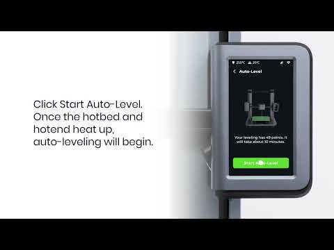
9. Power on the printer and start the auto-leveling process. Please refer to the following article and video for detailed instructions:
10. After the auto-leveling process is completed, the printer is now ready to start printing a new task.
III. Nozzle Carbon Accumulation / Nozzle Wear and Tear
The nozzle is clogged with carbon and the issue can only be resolved by replacing the nozzle. Please refer to the following article and video for detailed instructions:
- Article: How to Replace the Nozzle for the M5C Printer
- Video: How to Replace the Nozzle for the M5C Printer
IV. Throat Tube Internal Wear and Tear
The throat tube is worn internally and the issue can only be resolved by replacing the hot end. Please refer to the following article and video for detailed instructions:
- Article: How to Replace the Hotend for the M5C Printer
- Video: How to Replace the Hotend for the M5C Printer
If you have any further questions, please contact us for assistance.