Filament Cannot Pass the Filament Detection Sensor of M5
Identifying Issues:
- Filament cannot be inserted through the filament break detection switch
Reasons:
- Filament blockage at the break detection switch
- Filament blockage at the filament pipe connection after the break detection switch
Method for Addressing Filament Blockage at the Switch:
- Ensure the filament has been removed. Use an H2.0 hex wrench to unscrew the upper bolt on the left shoulder back cover and the two bottom bolts on the left shoulder.


Left button back cover
Bottom of left shoulder
- Open the left shoulder cover from back to front, and unplug the break detection line.

- Use an H2.0 hex wrench to unscrew the two long bolts on the break detection module and remove the module.

- Remove the break detection switch. Use a cross screwdriver to unscrew the two front cover fixing bolts, and remove the front cover.


- Separate the upper and lower covers of the break detection switch and remove the filament blockage.


- Reinstall the break detection switch.
- Reattach the left shoulder cover and use an H2.0 hex wrench to tighten the upper bolt and the two bottom bolts of the left shoulder.
- Load the filament, and click Control > Extrude > Load on the screen to check if the filament break detection module is installed and if the M5 can run normally.
Method for Addressing Filament Blockage at the Filament Pipe Connection:
- Ensure the filament has been removed. Use an H2.0 hex wrench to unscrew the upper bolt on the left shoulder back cover and the two bottom bolts on the left shoulder.


Left button back cover
Bottom of left shoulder
- Open the left shoulder cover from back to front, and unplug the break detection line.

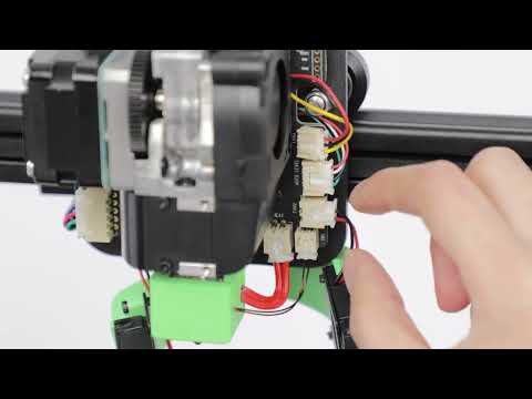
- Remove the Type-C cable and use a 1.5 hex wrench to release the Type-C cable guide buckle fixing bolt. Remove the green claw and pull out the filament pipe.


- Remove the cover of the Type-C cable guide buckle and use tweezers to remove the filament blockage.

- Reinstall the Type-C cable guide buckle upper cover, lock the retaining bolt with a 1.5 hex wrench, install the claw, insert the filament pipe, and reinstall the Type-C cable to the guide buckle.


- Reattach the left shoulder cover and use an H2.0 hex wrench to tighten the upper bolt and the two bottom bolts of the left shoulder.
- Load the filament, and click Control > Extrude > Load on the screen to check if the filament break detection module is installed and if the M5 can run normally.
If you have any further questions, please contact us for assistance.
119 undefined

M5C X Axis Belt Adjuster.gcode
Ankermake Studio Guide(V1.5.21)
M5C Y axis belt adjuster.gcode
V8110 AnkerMake M5C EU Declaration of Conformity
V8110_UK Declaration of Conformity
M5C Y Axis Belt Adjuster.gcode
View More

How to Replace the Air Guide of the Print Model Fan
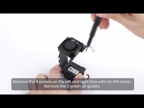
How to Replace the Print Model Fan

Auto Leveling
V Wheel Adjustment
How to Transfer Files and Start Printing
Loading Filament
View More