Video link:youtube.com/watch?si=QOGR2t3Uokugz9wf&v=ooBvM5V7Oj4&feature=youtu.be
Installation and Commissioning
-
Installation Environment Requirements
-
During installation of the roll-to-film accessory, sufficient opening width must be reserved for the double door panels. The roll-to-film accessory must be zeroed, and the rear door panel may be closed after zeroing is completed.
-
The installation printing environment should be consistent with that of the main unit, with a temperature range of 15°C–35°C and a humidity range of 20%–85%.
-
The roll-to-film accessory does not have an independent power cord and operates through the quick-release structure of the main unit after installation.
-
Debugging Process and Precautions
-
Material fixing and waste issue
Due to the roll-to-film accessory's structural design, a blank area of approximately 15–20 cm will remain at the start of each print. It is recommended to print continuously or use longer-format artwork whenever possible. The unused blank section may also be reused by placing it on the flatbed platform for printing.
-
Cutter operation
This function uses a built-in mechanical linear blade integrated into the roll-to-film accessory; no laser is required. After each print job is completed, or when the cutting function is activated during printing, the blade performs a straight cut along the X-axis to separate the finished output from the film roll. The operation is fast and precise, making it suitable for continuous or batch production.
-
Roll deviation and film alignment issues
-
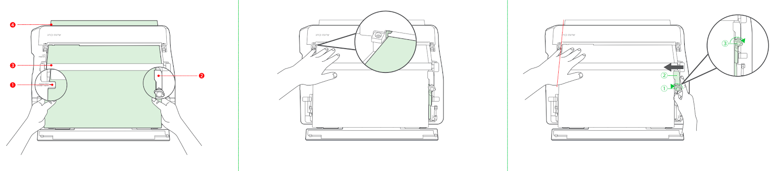
To prevent material deviation during roll-to-film printing, the film roll must be installed and operated in accordance with the QSG. The film roll should be positioned tightly against the left side. The film material should be pulled out and sequentially guided through the film sensor, feed shaft, and discharge shaft. The limit block must be positioned tightly against the right side of the film to prevent lateral movement.
-
During the four push–twist–press operations, use your hand to align the film material to the left against the green stop, then sequentially push, twist, and press down the four pressure rods to fix the film.
-
During the installation of the film roll onto the feeding shaft, resistance may be encountered. This is normal and is caused by friction-enhancing patterns on the shaft belt beneath the roller. Adjusting the threading technique will allow normal installation.
-
Finished product contamination
-
During long-format continuous roll-to-film printing, cut output may fall onto the table or floor and become soiled. It is recommended to place a clean collection box at the discharge outlet during printing.
-
After printing with soft white ink during the gold stamping process, the surface may remain slightly tacky. Avoid stacking printed output during long-format printing, as this may cause damage.
-
Precautions for installing the roll-to-film accessory
-
When installing the film roll, place it directly onto the support rollers. Push the roll gently into position without force or shaking, as excessive force may cause misalignment and printing failure.
-
When installing the roll-to-film accessory onto the main unit, do not invert the accessory or allow the film roll to shift, as this may cause misalignment and result in printing failure.
-
During roll-to-film printing, ensure that printed output can fall freely from the cutting position. If the output remains at the cutting point, subsequent cuts may overlap, potentially causing cutter blockage, damage, or cutting failure.
-
After roll-to-film printing and gold stamping, avoid stacking non-gold-stamped areas with other printed parts, as this can cause the gold-stamped surfaces to adhere and lead to product failure
-
Common Installation Issues and Solutions
-
Film roll not detected
-
Check whether the film roll is positioned tightly against the left side and whether the sensor at the roll placement position is triggered. If misalignment is detected, reposition the film roll before printing.
-
Check whether the film material is installed correctly, paying particular attention to alignment. Confirm that in-position detection is triggered. If the film material is installed incorrectly, reinstall it.
-
Caliper measurement
-
Standard substrate:
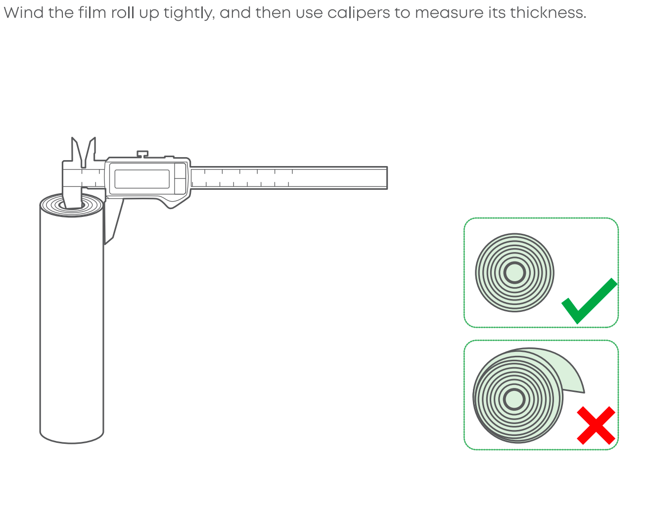
A vernier caliper is included with the roll-to-film accessory. Measure the diameter of the film roll and input the measured value into the software. After selecting the corresponding roll type, the system will calculate the remaining film length.
(Ensure the film roll is tightened.)
-
Non-standard substrate:
For non-standard substrates, use a vernier caliper to measure film thickness, roll diameter, and film roll diameter. These values are used to calculate the remaining length of the film roll.
(Ensure the film roll is tightened.)
Software Operation Guide
-
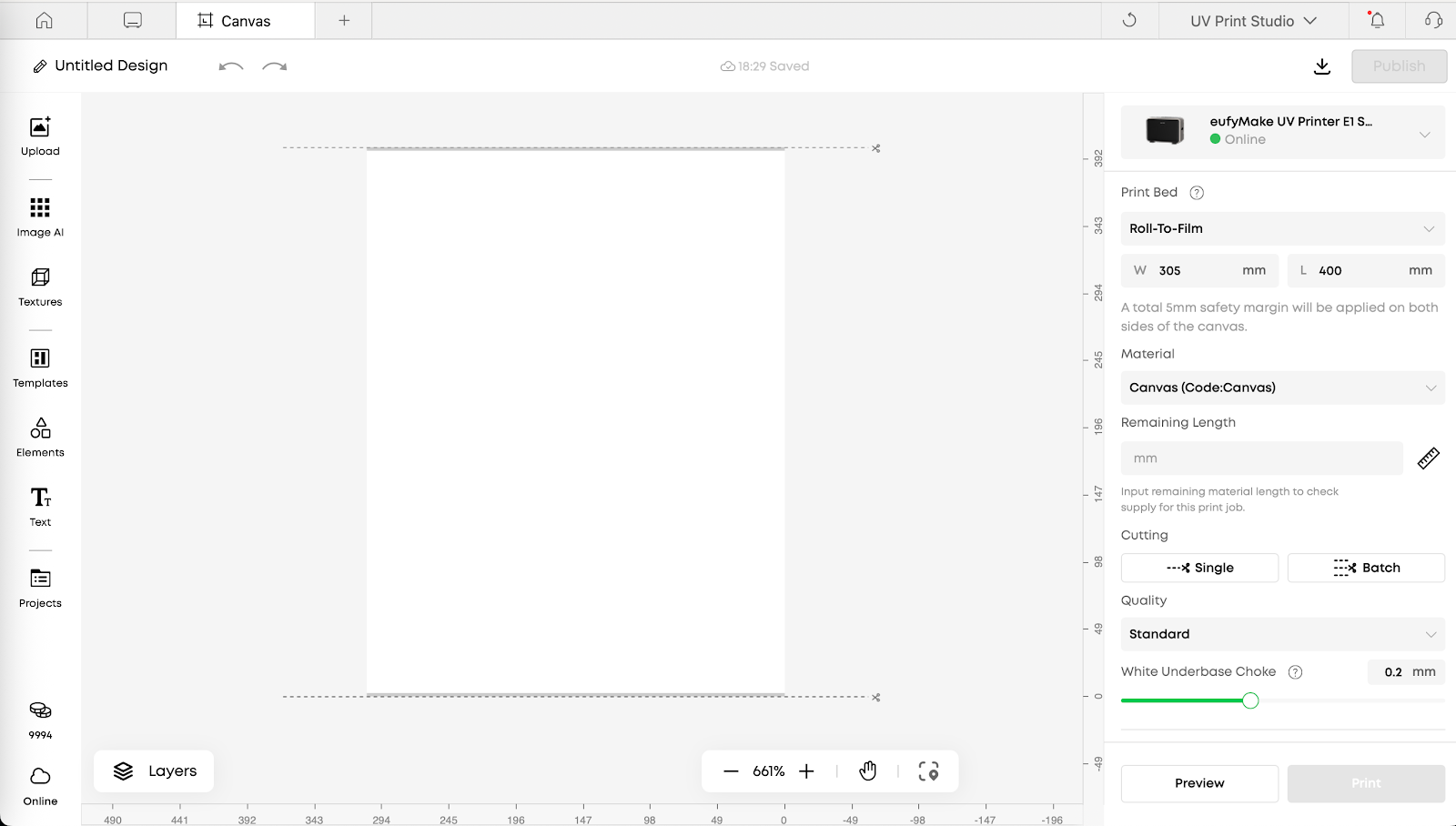
Operating Instructions
The main operating interface for roll-to-film printing is similar to that of other platforms. The following sections focus on applying process modes to supported roll-to-film materials and on roll-to-film–specific functions.
-
Introduction to Roll-to-Film Craft (Craft Mode)
When using ink modes that include white ink (e.g., White > CMYK or Color Raised), flexible white ink must be used. Using hard white ink may cause contraction or curling of flexible film materials.
Flat Mode:
-
When printing on roll-to-film substrates using the Flat process, CMYK Ink Mode is recommended. Both polymeric vinyl and canvas have white base layers, resulting in similar output when using CMYK or White > CMYK. CMYK conserves ink and eliminates the need to switch to flexible white ink.
-
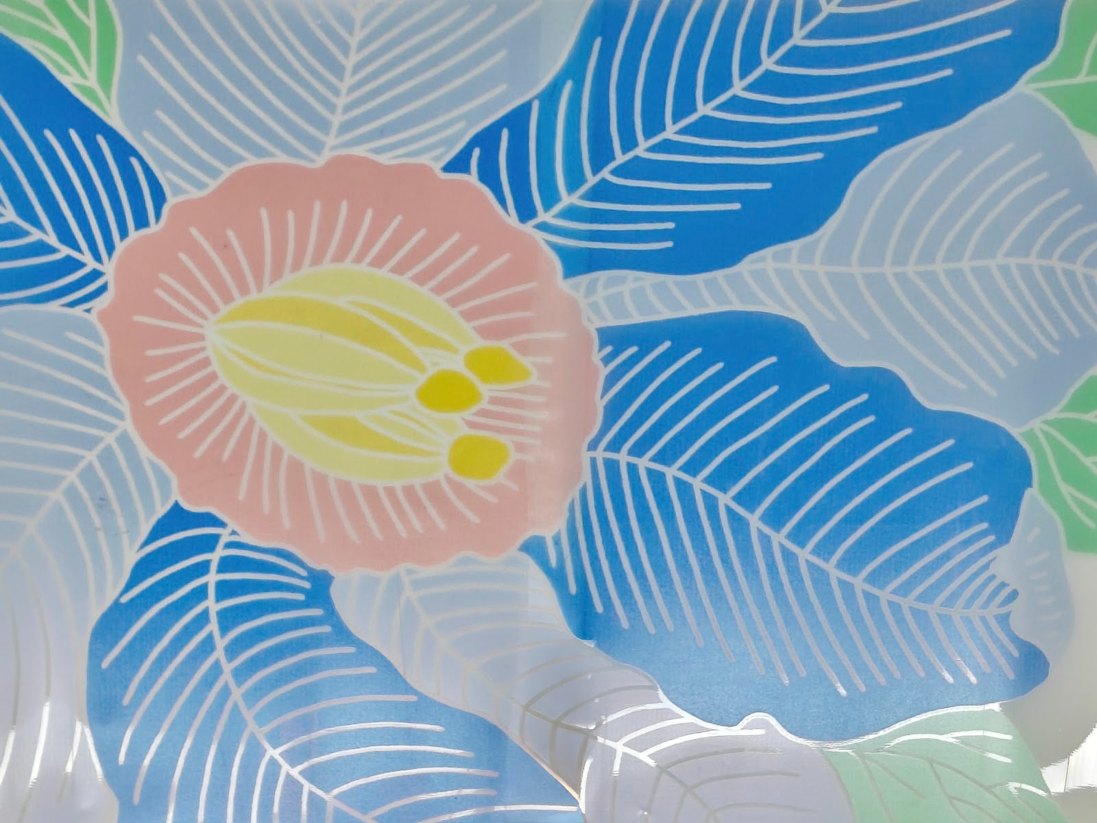
Printing Ultra-Clear UV Vinyl in CMYK produces a light-transmitting effect. Selecting ink modes that include white ink will eliminate this effect. Different ink layer selections will significantly affect color depth and may be adjusted based on preference.
-
Gloss varnish is not supported for roll-to-film printing, as it may cause contraction and curling of the film material.
-
2.5D modes include Flat Raised, Pattern Texture, Relief Texture, and Custom Texture.
-
Common Functions and Operating Procedures
-
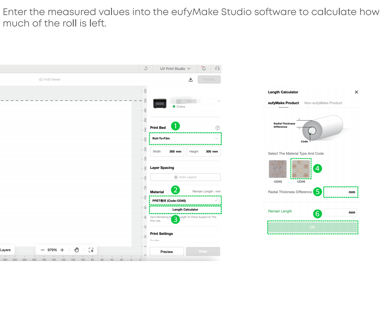
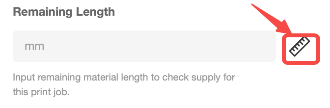
Media Length Calculator
-
This tool is used to track the remaining length of roll-to-film media.
-
Purpose: Confirms whether sufficient film remains for the current print job, preventing failures due to insufficient material.
-
Function: Calculates the remaining length of the current film roll.
-
How to use: When changing film rolls, click the ruler icon to open the Media Length Calculator. Select the media type, then follow the on-screen instructions to measure the remaining length with calipers. If the length is already known, it may be entered directly. The remaining length updates automatically after each print job. Recalculation is required whenever the film roll is replaced.
-
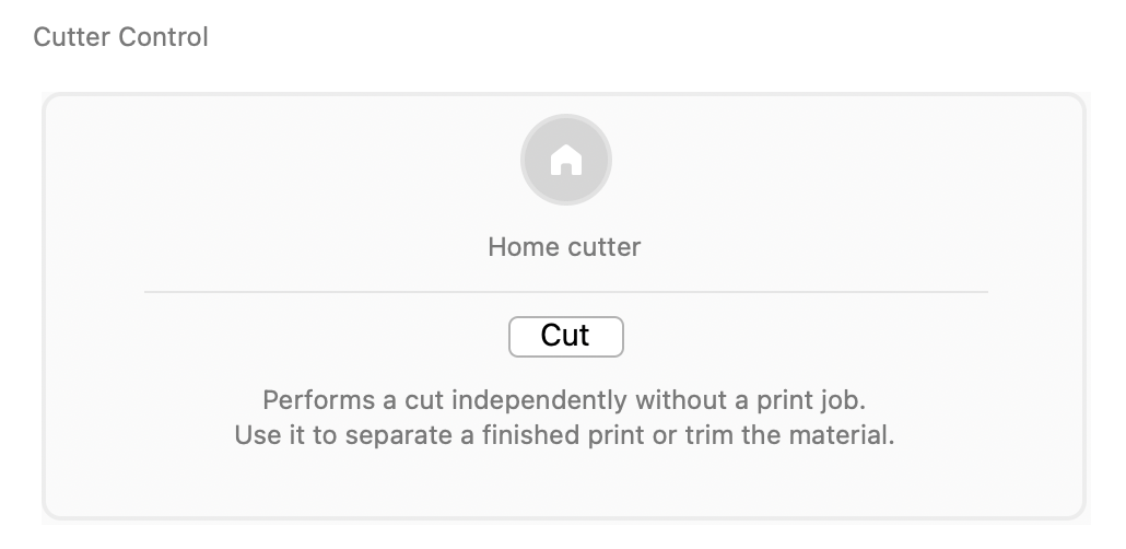
Cutter Settings
After printing is complete, the built-in cutter can be used to trim the printed film.
-
Purpose / Function: Cuts the film media at designated positions.
-
How to use: During design, set the number and positions of cuts as needed.
-
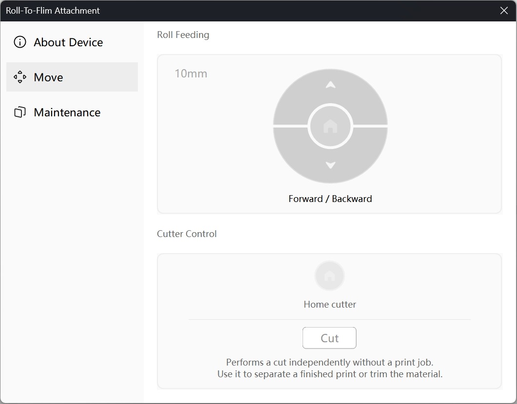
Manual cutting is also available through the Roll Feeder menu without starting a print job.
-
Manual Forward and Backward Control of the Film / Cutter
-
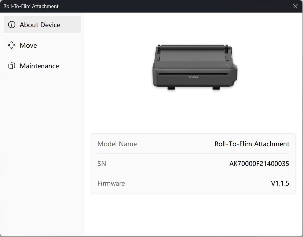
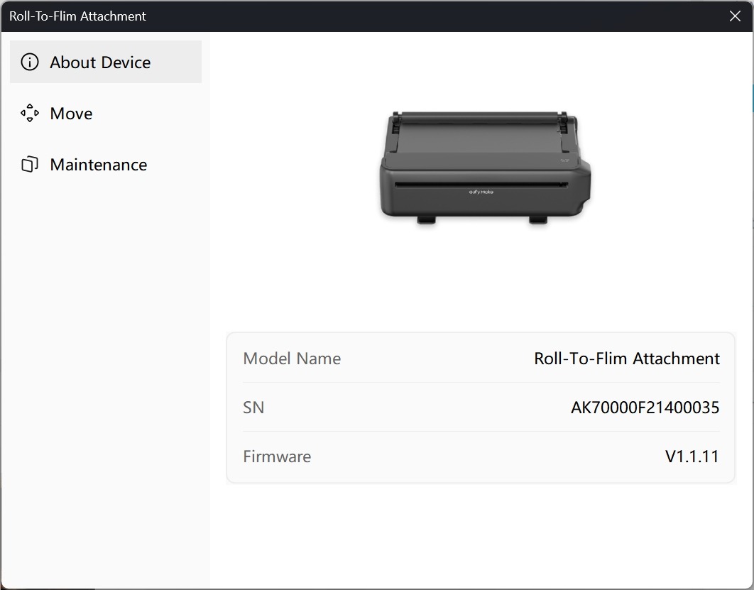
Roll-to-Film Accessory Firmware Upgrade
The firmware for the roll-to-film accessory is upgraded together with the printer firmware. After the printer upgrade is completed, installing the roll-to-film accessory will automatically trigger the accessory firmware update.
To view the firmware version and serial number of the roll-to-film accessory:
Go to the device management homepage → click Accessory Management in the upper-right corner → view the information in the pop-up window.